


A wire harness bundles multiple wires, connectors, and terminals inside a single protective jacket. That lets you wire a piece of equipment with one assembly instead of dozens of loose conductors. Getting the wire harness assembly process right makes the difference. It separates a harness that survives ten years of vibration and thermal cycling from one that fails at the first field inspection. This guide walks through the eight manufacturing steps and the materials involved. It also covers IPC/WHMA-A-620, the industry standard that governs how each step gets inspected and accepted.
Every step below is cross-referenced to the current IPC/WHMA-A-620 revision and to the acceptance class (Class 1, 2, or 3) it is evaluated against, so engineers sourcing a harness can see exactly which clause governs which workmanship check — not just that “a standard applies.

Designing a Wire Harness Before the Assembly Process Begins
Every wire harness assembly process starts on paper, or more precisely, in CAD. Engineers review the application’s electrical requirements first: current load, voltage, operating environment, and connector interfaces. From there, they build a schematic and a full-scale layout drawing, often called a “harness board” drawing. That drawing defines exactly how long each wire needs to be, which connector goes where, and how the bundle routes through the enclosure.
This drawing becomes the reference document for everything downstream. Production staff pull strip lengths, wire colors, and terminal call-outs directly from it. Quality inspectors use the same drawing to verify the finished harness. Without an accurate drawing, a team can’t reproduce the harness consistently, and troubleshooting it later becomes much harder. See our Design & DFM guide for more on getting this stage right before tooling begins.

The Wire Harness Assembly Process: 8 Manufacturing Steps
1. Cutting and Stripping Wires
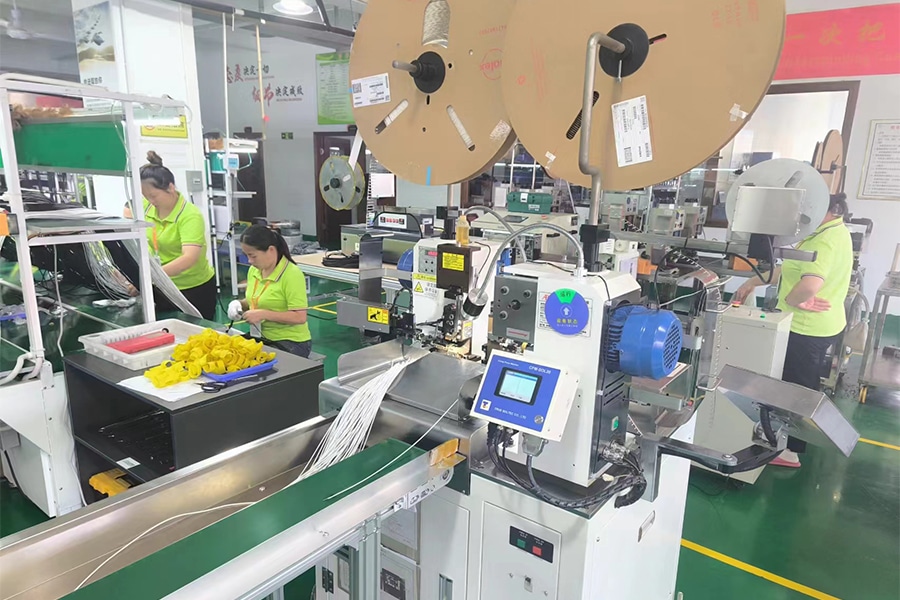
Automated machines cut each wire to the length the harness drawing specifies. They then strip a precise length of insulation from each end to expose bare conductor for termination. Strip length matters more than it sounds. Too short, and the terminal can’t make full contact with the conductor. Too long, and exposed copper can short against an adjacent wire or the harness housing. IPC/WHMA-A-620 sets tolerances for strip length and prohibits nicked or scraped conductor strands. A nicked strand becomes a stress point, and the wire can eventually break there under flex or vibration.
IPC/WHMA-A-620’s wire-preparation criteria classify a nicked or scraped strand as a workmanship defect regardless of acceptance class, and set the allowable strand damage at a fraction of the conductor’s diameter. Romtronic’s cut-and-strip stations record length and strand-damage data on every cycle, so a strip-length deviation is caught before the wire reaches crimping — not discovered later at final inspection.
2. Crimping or Soldering
With the wire ends prepared, technicians attach terminals using one of two methods. Crimping mechanically compresses a metal terminal around the stripped conductor. Soldering bonds the terminal with molten solder instead. Crimping dominates high-volume production because it’s fast and produces a consistent, gas-tight connection when done correctly. Soldering tends to show up where a connection needs to withstand extreme vibration, or where a legacy design specifically calls for it.
This step is where IPC/WHMA-A-620 does most of its work. The standard defines acceptable crimp height, crimp width, and conductor visibility inside the crimp barrel. It also sets pull-test force requirements that confirm the termination will hold under mechanical load. Where technicians solder, the workmanship criteria align with IPC J-STD-001, so nobody’s working from two different rulebooks depending on the connection method. See our guide to different types of wire harness terminals for how terminal choice affects this step.
Minimum acceptable pull-test force scales with wire gauge under IPC/WHMA-A-620 — inspectors compare each sampled crimp against the force table for that AWG size, not a single blanket number. Romtronic logs crimp height, width, and pull-force results per lot as part of its traceability package, available to customers on request.

3. Terminal Assembly
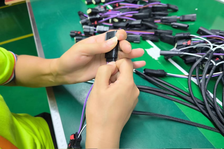
Once crimped or soldered, technicians insert terminals into their connector housings and mechanically lock them in place. A retention tang or a secondary locking wedge typically does the locking, keeping the terminal from backing out under vibration. An improperly seated terminal is one of the more common field failures in wire harness assemblies. It can pass a visual check and still pull loose the first time the harness flexes.
Inspectors verify seating with a gentle tug test on every cavity. Higher-reliability programs pull-test a sampled percentage of terminals against a documented force spec. This step also confirms connector polarization, so mismatched connectors can’t mate incorrectly in the field.
4. Routing and Bundling the Harness
Operators lay the individual wires out on a harness board according to the routing drawing. They then bundle the wires together with cable ties, harness tape, or spiral wrap. The bend radius and branch-point locations follow whatever the design calls for. Bundling isn’t just cosmetic. A tightly organized bundle resists abrasion better and routes more predictably through an enclosure. It’s also far easier to trace during troubleshooting than a loose tangle of wires.
Minimum bend radius matters here too. Bundle a harness too tightly around a corner, and repeated flexing can fatigue the conductors inside, even if the outer jacket looks fine. That’s part of why routing drawings specify bend radius alongside wire length in the first place.
5. Testing and Inspection
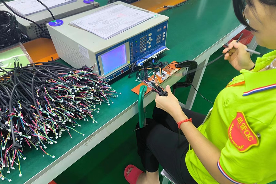
Before a harness moves further down the line, it goes through electrical testing on specialized fixtures. A continuity and hipot (high-potential) test confirms every circuit connects where the drawing says it should, and that insulation resistance meets spec. This step catches wiring errors, shorts, and opens early, before they turn into a far more expensive problem on an assembled product.
Inspectors also run a visual check alongside electrical testing. They compare crimps, solder joints, routing, and labeling against IPC/WHMA-A-620’s target and acceptable conditions. The applicable acceptance class, Class 1, 2, or 3, depends on how critical the end application is. Customer and manufacturer should agree on that class before production starts, not decide it ad hoc on the inspection floor. Our Testing & Validation hub covers these fixtures and acceptance methods in more depth.
| Acceptance Class | Typical Application | Core Requirement |
|---|---|---|
| Class 1 | General consumer electronics | Must simply function |
| Class 2 | Industrial/commercial equipment (most use cases) | Must deliver extended service life under normal operating conditions |
| Class 3 | Aerospace, medical, military | Held to the strictest standards for continued or on-demand performance |
6. Applying Protective Covering
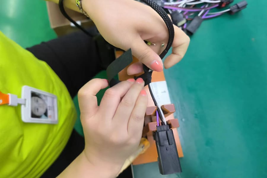
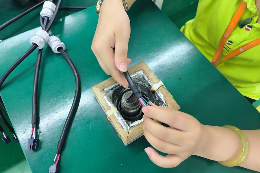
Technicians add braided sleeving, spiral wrap, or heat-shrink tubing over sections of the harness that need extra protection. Abrasion, chemical exposure, and temperature extremes are the usual reasons. They also use heat-shrink tubing at individual termination points. It insulates the connection and provides basic strain relief where a wire enters a terminal or splice.
The right covering depends heavily on where the harness ends up. A harness routed through an engine bay needs different protection than one running inside a climate-controlled enclosure. In that sense, this step is really an extension of the original design requirements, not a generic finishing touch. Our comprehensive guide to heat-shrink tubing covers material choices for this step in detail.
7. Labeling and Marking
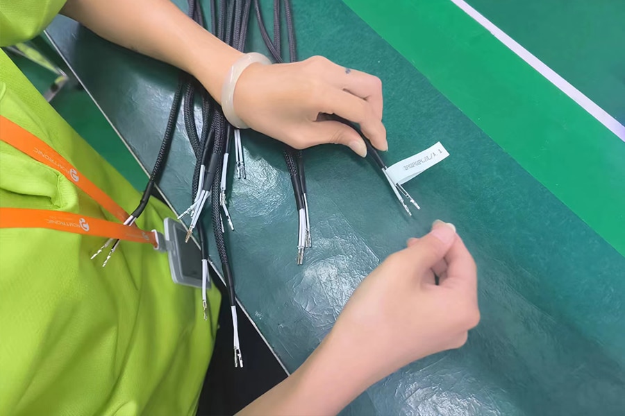
Technicians identify every wire and connector, usually with printed heat-shrink labels, adhesive labels, or ink-jet marking directly on the wire jacket. The labels match the designators on the harness drawing. Consistent labeling sounds like a minor step, but it lets a field technician diagnose a fault in minutes instead of hours. It also lets a manufacturing line trace a defect back to the correct wire and connector during a corrective action.
IPC/WHMA-A-620 includes marking legibility and durability requirements as part of its acceptance criteria. A label that fades or rubs off within a year defeats the purpose of labeling in the first place.
8. Final Quality Approval and Packaging
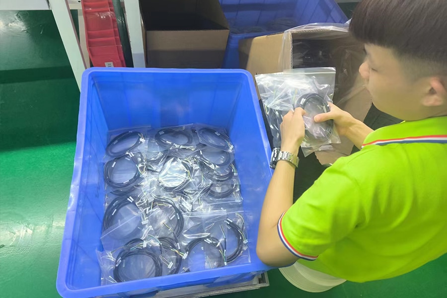
Once the harness clears final inspection against the agreed acceptance class, it moves to packaging. For most wire harnesses, that means careful hand-wrapping to prevent connectors from getting damaged or contaminated in transit. Some programs also require a final documentation package: test records, inspection sign-off, and traceability data tying the harness back to its production lot.
At this point the harness is ready to ship. Everything upstream, from the original drawing to the final pull test, exists so that what arrives at the customer’s dock matches the drawing exactly.
Materials Used in the Wire Harness Assembly Process
A typical wire harness combines several material categories, each chosen for the application rather than picked generically. Conductors are usually copper, valued for its conductivity and flexibility, though aluminum shows up in weight-sensitive applications. Connectors and terminals vary by current rating, environmental sealing needs, and mating cycle life. Engineers select protective covering, PVC, polyethylene, braided sleeving, or heat-shrink tubing, based on temperature range, chemical exposure, and abrasion resistance in the final installation.
These choices interact with each other. A higher-current conductor needs a terminal rated for that current, which in turn needs a housing sized to fit it. That’s why material selection happens during the design phase covered earlier, not as an afterthought during assembly.
Off-the-Shelf vs. Custom Wire Harness Assembly
Not every application needs a fully custom wire harness assembly process from scratch. Manufacturers pre-design off-the-shelf harnesses and mass-produce them to common specifications. They typically ship faster than a custom design-and-build cycle allows, since there’s no drawing review or tooling lead time to wait through. For standard applications, where an existing harness already fits the connector footprint and current requirements, that speed and cost advantage is hard to beat.
Custom harnesses earn their higher cost and longer lead time when the application has requirements a stock harness can’t meet. That includes unusual routing, specific connector combinations, or tight space constraints. It also includes certification requirements, medical, automotive, or aerospace, that call for a documented, traceable build process from day one. See our custom wire harness page for the application categories we build for.
Automating the Wire Harness Assembly Process
Automated equipment now handles the most repetitive, precision-dependent parts of the wire harness assembly process. Cutting, stripping, and crimping lead the list, since consistency matters there more than judgment. A cut-and-strip machine holds tighter length and strip tolerances across thousands of cycles than a manual process realistically can. Automated crimp presses also log force and height data on every cycle, which supports the traceability that higher-reliability programs require.
That said, automation hasn’t replaced manual work entirely. Routing, bundling, and final inspection still rely heavily on trained technicians. That’s especially true for harnesses with complex branch points or tight bend-radius requirements that don’t lend themselves to fixed tooling. Robotics and data analytics are steadily expanding automation’s role in those areas too. For now, though, the wire harness assembly process runs as a hybrid: automated precision paired with manual craftsmanship. Our Manufacturing Control hub covers how we manage that mix on the production floor.
IPC/WHMA-A-620: The Standard Behind the Wire Harness Assembly Process
Nearly every acceptance criterion mentioned above traces back to one document: IPC/WHMA-A-620, Requirements and Acceptance for Cable and Wire Harness Assemblies. IPC and the Wire Harness Manufacturers Association developed it jointly. It’s the only industry-consensus standard covering the full wire harness assembly process, from wire preparation and crimping through soldering, connector assembly, marking, shielding, and final testing.
The standard defines three acceptance classes, and the applicable class changes what “acceptable” actually means for a given harness:
- Class 1 covers general electronic products where the primary requirement is that the assembly functions.
- Class 2 applies to assemblies expected to deliver extended service life under normal operating conditions. Most industrial and commercial applications fall under this class.
- Class 3 applies to high-reliability products: aerospace systems, medical devices, and military electronics, where continued performance or performance-on-demand is critical.
Romtronic builds to Class 2 (or Class 3 for high-reliability programs) and verifies its process against the current IPC/WHMA-A-620F revision, released in 2025, which aligned soldering requirements with IPC J-STD-001 and reorganized the standard’s chapter structure — so criteria for crimped, soldered, and mechanically secured connections now live in one consistent framework instead of two separate rulebooks.
These process controls sit alongside Romtronic’s IATF 16949 and ISO 13485 quality-management certifications, and customers can request the applicable acceptance-class agreement, crimp force/height records, and continuity-test data as part of the final documentation package described in Step 8 above. See our Standards & Compliance hub for the full list of standards we build to.
FAQ
A: It covers the full wire harness assembly process: wire preparation, crimped and soldered terminations, connector assembly, routing and bundling, labeling, shielding, and final inspection criteria. It doesn’t cover wire cross-section evaluation or X-ray inspection, which fall under separate guidance.
A: Class 2 assemblies are built for extended service life under normal operating conditions, the standard most industrial and commercial wire harnesses are held to. Class 3 is reserved for high-reliability applications, aerospace, medical, and military, where the acceptance criteria are noticeably tighter.
A: A strip that’s too short limits how much conductor the terminal actually grips, weakening the connection. A strip that’s too long leaves bare copper exposed, which can short against a neighboring wire or the harness housing. IPC/WHMA-A-620 sets tolerances specifically to avoid both failure modes.
A: Off-the-shelf is faster and more cost-effective when an existing harness already matches your connector and current requirements. Custom makes sense when your application has routing, space, connector, or certification requirements that a stock harness can’t satisfy.
A: Yes — on request, Romtronic includes crimp height/pull-force data, continuity and hipot test results, and the agreed acceptance-class sign-off as part of the final documentation package, tied to the production lot.
A: Timelines vary with harness complexity and volume, but the sequence itself — drawing sign-off, cutting/stripping, crimping, assembly, testing, and packaging — is fixed. Contact our engineering team with your drawing for a project-specific lead time.
.avif)
Sam Wu is the Marketing Manager at Romtronic, holding a degree in Mechatronics. With 12 years of experience in sales within the electronic wiring harness industry, he manages marketing efforts across Europe. An expert in cable assembly, wiring harnesses, and advanced connectivity solutions, Sam simplifies complex technologies, offering clear, actionable advice to help you confidently navigate your electrical projects.

