


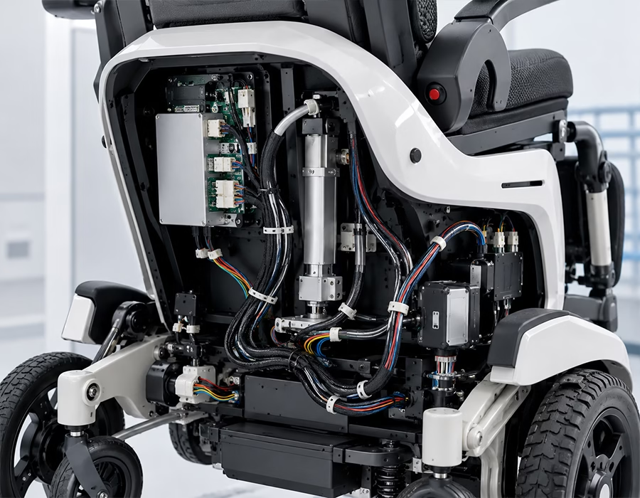
If you build powered wheelchairs, exoskeletons, or robotic therapy equipment, the wiring inside your rehabilitation and mobility devices has to handle a lot more abuse than anything sitting on a hospital cart. Here’s how we build harnesses that hold up.
Why Wiring for Rehabilitation & Mobility Devices Is a Different Animal
First off, let’s be clear about what makes this category so tough. A hospital IV pump sits still on a cart all day. A powered wheelchair, on the other hand, gets bounced down curbs, tilted by a rider shifting their weight, and rained on in a parking lot. So, naturally, rehabilitation and mobility devices need wiring that’s built for constant motion, not for sitting still.
Consequently, if a control harness cracks from fatigue, that’s not just an inconvenience — a patient can end up stranded, or worse, in real danger. That’s exactly why, at Romtronic, we engineer internal wiring specifically for rehabilitation and mobility devices: assemblies that shrug off mechanical shock, multi-axis vibration, and outdoor weather. If you’re also sourcing wiring for other medical equipment, our Medical Wiring Harness page covers the broader category.
Packing High Current Next to Sensitive Sensors
Here’s the tricky part: mobility systems pack high-capacity battery power right next to microvolt-level feedback sensors, all in the same tight enclosure. As a result, that combination demands careful cable design, so the high current draw doesn’t drown out the delicate signal lines.
To solve that, we build every harness for rehabilitation and mobility devices around three things:
- Dual-zone power and logic separation. Specifically, we run heavy-gauge motor lines (12 AWG to 16 AWG) alongside fine-gauge feedback lines (28 AWG to 32 AWG) in a single shielded harness, without one corrupting the other.
- Joints that flex without breaking. For active orthotics and exoskeletons, we use tinsel-wire construction that bends across a human joint thousands of times without work-hardening or snapping.
- Sealed against rain and washdowns. Because these devices get rained on, splashed, and sometimes power-washed, we overmold joystick and battery connectors to an IPX6-rated, watertight seal.
Material & Compliance Cheat Sheet for Rehabilitation & Mobility Devices
| Mobility Sub-System | Material Solution | Why It Matters |
|---|---|---|
| Robotic exoskeleton hinges | Tinned copper-clad steel with PTFE wrap | Cuts friction so the wire doesn’t bind inside tight, moving joint housings |
| Power wheelchair joysticks | Heavy-wall TPU jacket with molded strain relief | Handles constant tugging, impact, and outdoor UV exposure |
| Actuator & battery links | High-strand, low-resistance silicone-insulated conductors | Survives sudden high-amp surges, like hill climbing, without overheating |
| Patient harness sensors | ISO 10993 compliant elastomeric overmolds | Keeps prolonged skin contact safe against sweat, heat, and friction |
Every build also runs through our ISO 13485 certified quality system — you can see the full breakdown on our Certifications page.
The Two Failures That Wreck Most Mobility Device Harnesses
Vibration Fatigue at the Crimp
Powered mobility platforms take constant low-frequency vibration from bumpy pavement and motor feedback. Over time, that vibration causes micro-fretting at the crimp terminal. Consequently, copper strands work-harden and snap inside the connector, which shows up as intermittent power loss — usually at the worst possible moment.
So, we counter it with automated crimping under pull-force monitoring, plus a high-viscosity potting compound around the terminal back. In short, that combination dampens vibration before it ever reaches the copper.
Motor Noise Bleeding Into the Joystick
Meanwhile, brushed DC motors and high-torque actuators throw off serious electromagnetic interference (EMI) when they accelerate. If that noise bleeds into the joystick controller lines, it creates false voltage signals — and that can make a wheelchair or robotic arm jerk or stutter unpredictably, which is obviously not something you want near a patient.
To stop this, we wrap every low-voltage signal path in a double-shielded layer: a 95%+ coverage tinned copper braid plus an aluminum foil wrap. This keeps the dirty motor field isolated and the joystick signal clean.
FAQ: Rehabilitation & Mobility Device Wiring
Usually, it’s electromagnetic interference from the drive motor bleeding into the joystick’s signal lines. Shielding the signal path with a tinned copper braid and a foil wrap, and keeping it away from motor lines, generally solves it.
Standard hookup wire work-hardens fast under repeated flexing. Instead, we use tinsel-wire construction, which is built specifically to survive thousands of flex cycles at a moving joint without snapping.
If the device is a regulated medical product, then yes, your suppliers should be building under ISO 13485. We build every rehabilitation and mobility device harness under that certification as standard, not as an upcharge.
An IPX6 rating means the connector can handle heavy rain and splashing without water getting in. We achieve that with high-pressure overmolding directly around the joystick and battery terminations.
Send your 2D wiring schematic, mechanical drawing, or BOM to our Engineering Hub, and our team will flag wear points and get you a quote within 24 hours.
Send Us Your Schematic
To sum up, if you’re dealing with wire breaks at moving joints, water getting into joystick modules, or motor noise causing erratic control on your rehabilitation and mobility devices, let’s fix it. Upload your 2D schematics, mechanical blueprints, or BOM to our Engineering Hub, or check our FAQ for quick answers. Afterward, our engineering team will run a full DFM analysis and get you a tailored quote within 24 hours. You can also reach us directly through our Contact page.