


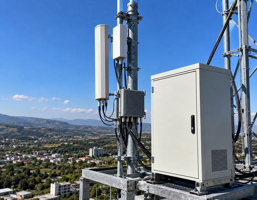
Outdoor Durability Meets Microwave-Grade Signal Purity
A cellular base station lives a rough life. It sits on a tower or rooftop through years of sun, rain, wind, and temperature swings, while still needing to pass a clean RF signal with almost zero distortion. Get the cabling wrong, and the failure isn’t always obvious right away. Sometimes it just shows up as dropped calls, degraded data throughput, or a mystery interference complaint nobody can trace back to a cause.
We design and manufacture RF cable assemblies specifically for cellular base station and telecom infrastructure builds. Our custom interconnects cover feeder cables, jumpers, hybrid fiber-power runs, and grounding kits, all engineered for outdoor survival and low passive intermodulation.
We bring 29 years of OEM/ODM experience to telecom infrastructure projects. As a high-mix, low-volume (HMLV) contract manufacturer, we build everything from a single custom jumper to a full site cabling kit, so tower crews aren’t stuck sourcing parts from five different vendors.
- ISO 9001 factory validation. Every cellular base station assembly runs through our certified quality pipeline before it ships.
- IPC-A-620 Class 2/3 workmanship. RF connector termination, cable prep, and hybrid cable assembly all meet a documented, repeatable quality standard.
- Low-PIM design and testing. We test to IEC 62037 passive intermodulation standards, since even a loose connector or contaminated contact surface can generate PIM that degrades an entire sector’s performance.
- Weatherproof, UV-stable jacketing. Our outdoor cable jackets resist years of UV exposure, temperature cycling, and moisture ingress without cracking or embrittling.
Technical Specifications and Manufacturing Matrix
| Parameter | Manufacturing Capability | Validation / Material Standards |
|---|---|---|
| Workmanship standard | IPC/WHMA-A-620 Class 2/3 | Certified IPC workmanship |
| Quality management | ISO 9001 factory certified | Third-party audited and documented |
| Connector types | N-type, 4.3-10, DIN 7/16, SMA | Compatible with Amphenol, Rosenberger, or custom overmolds |
| PIM performance | -150dBc or better, tested per IEC 62037 | Torque-controlled assembly to prevent loose-contact PIM |
| Feeder cable types | 1/2″, 7/8″ coaxial, low-loss foam dielectric | 50Ω impedance, VSWR ≤1.15:1 typical |
| Hybrid fiber-power cables | Combined DC power + fiber for RRUs | Single-jacket delivery to remote radio units |
| Environmental sealing | IP68 overmolded connector boots | Survives outdoor UV, moisture, and temperature cycling |
| Functional verification | VNA-based VSWR, insertion loss, and PIM testing | Full traceability per batch |
Six Base Station Cabling Types We Build For
We design, tool, and assemble interconnects across six core categories for cellular base stations:
- RF feeder and jumper cable assemblies. Low-loss coaxial feeders run from the radio to the antenna, and short flexible jumpers absorb mechanical stress at each connection point without stressing the main run.
- Hybrid fiber-power cables for remote radio units (RRUs). A single jacket carries both DC power and fiber data to the radio mounted near the antenna, cutting installation time versus pulling separate cables. Our LEMO-based fiber/coax combination assemblies are built for exactly this kind of telecom equipment.
- Tower-mounted amplifier (TMA) interconnects. Short, low-loss jumpers connect TMAs to the antenna and radio, engineered to hold PIM performance despite constant tower vibration and thermal cycling.
- 5G small cell and macro site cabling. Compact, high-density RF and fiber runs fit tight enclosure spaces on light poles, rooftops, and macro towers alike.
- In-building distributed antenna system (DAS) cabling. Indoor coaxial and fiber runs distribute signal through buildings and tunnels, built for tight conduit routing and long-term reliability behind drywall.
- Grounding and lightning protection kits. Bonded ground cables and kits protect base station electronics from induced surge currents during electrical storms.
Two Failure Modes We Design Every Base Station Harness Around
Passive Intermodulation (PIM) from Loose or Contaminated Connections
PIM is the quiet killer of cellular base station performance. When two or more RF signals mix at a poor connection point, a loose connector, dirty contact surface, or corroded interface, they generate intermodulation products that raise the site’s noise floor. That shows up as reduced coverage, dropped connections, or throughput problems that look like a network issue but actually trace back to a bad cable connection.
We control this with torque-specified connector assembly, proper bend radius management to avoid stressing the connector interface, and PIM testing per IEC 62037 on every finished assembly. That catches a marginal connection before it ever reaches the tower.
Moisture Ingress at Outdoor Connector Interfaces
Outdoor RF connectors face constant exposure to rain, humidity, and temperature-driven condensation. Even a small amount of moisture at the connector interface can corrode contact surfaces over time, and that corrosion often shows up first as a PIM problem rather than a dead short. We handle this with properly designed waterproof overmolds rated to IP68, sealing the connector joint completely against water intrusion.
Frequently Asked Questions
A: Passive intermodulation happens when RF signals mix at an imperfect connection point, a loose connector, or a corroded contact, and generate interference that raises a site’s noise floor. It’s a leading cause of coverage and throughput problems that look like network issues but actually trace back to cable or connector quality.
A: N-type, 4.3-10, DIN 7/16, and SMA connectors are the most common choices for outdoor RF feeder and jumper cables, with 4.3-10 becoming the default for many modern 5G deployments due to its smaller size and low-PIM performance.
A: A hybrid cable combines DC power conductors and fiber optic strands in a single jacket, feeding a remote radio unit (RRU) mounted near the antenna. This cuts installation time significantly compared to running separate power and fiber cables up the tower.
A: PIM testing follows the IEC 62037 series of standards, which define test methods and power levels for measuring intermodulation products generated by RF components. Reputable manufacturers test every finished assembly, not just a sample batch, since PIM problems often trace back to individual connector assembly quality.
A: Because PIM and connector degradation don’t cause a hard failure right away. Instead, they gradually raise the noise floor or introduce intermittent signal loss, which shows up in network performance data long before anyone traces it back to a specific cable or connector.
A: Yes, in every outdoor installation. Feeder cables, jumpers, and connector boots face years of direct sun exposure, temperature swings, and moisture, so the jacket and sealing materials need to resist UV degradation and water ingress without cracking over the life of the site.
Put Our RF Cabling Team to Work
Cellular network performance leaves zero room for a marginal connector or a hidden PIM problem. Whether you’re deploying a new 5G macro site, retrofitting legacy 4G infrastructure, or need a full site cabling kit shipped ready for tower crews, we can help.
Upload your site drawings, connector specs, or BOM directly to our Engineering Hub. Our team of 12 wiring engineers will run a full DFM audit and get a clean production quote back to you within 24 hours.
For general RF cable assembly fundamentals, our introduction to RF cable assemblies is a good starting point, and our piece on common RF cable failures and how to avoid them covers failure modes beyond PIM specifically.