


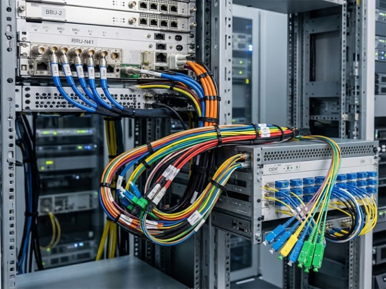
Romtronic builds communication equipment wiring harnesses for telecom equipment, including base station (RAN) cabinets, switch and router chassis, DC power distribution units, and optical distribution frames (ODFs). When you send us a drawing or sample, we build, label, and test each harness to IPC/WHMA-A-620 standards. Then we ship it ready to install.
IPC/WHMA-A-620 Class 2 or 3 · 100% electrical test · Prototypes in 5–15 business days · MOQ from 10 pcs
What are communications equipment wiring harnesses?
A harness is a pre-cut, pre-terminated bundle of power, RF, signal, and grounding conductors, each labeled at both ends. In other words, it replaces loose point-to-point wiring inside a cabinet or chassis. Since we test every circuit at the factory, your line installs the harness once instead of wiring and debugging by hand.
A wire harness is a branched assembly for the inside of an enclosure, while a cable assembly—often sourced as custom pre-connectorized cables—is a single cable factory-terminated at both ends for plug-and-play deployment. In practice, most telecom builds need both internal harnesses and external pre-terminated links, so we supply them together. See our Ethernet, DC, and power cables for matching cable assemblies.
Communications equipment wiring harnesses we build
| Type | Where it is used |
|---|---|
| RF coax jumper harness | Radio-to-antenna and filter jumpers in RAN and small-cell equipment |
| Backplane and card-edge harness | Chassis backplane to daughter cards, I/O panel wiring |
| −48 V DC / PDU distribution harness | Cabinet PDU to shelves and modules |
| Grounding and bonding harness | Rack and frame grounding in central office and outdoor cabinets |
| Fiber breakout / ODF pigtail assembly | Fan-out from fiber cable to connectorized pigtails |
| EMI-shielded I/O harness | Control and monitoring lines routed near RF or high-current power |
| BBU-to-RRU interconnect harness | Combined fiber, DC power and alarm conductors |
| Rack-to-rack interconnect | Pre-measured runs between cabinets |
| Alarm and environmental monitoring harness | Temperature, door, and smoke sensor wiring |
Our Custom-Made Wiring Harnesses for Communication Equipment
Each build started as a customer drawing or sample. If one looks close to what you need, let us know, and we will quote from there.
RF coax jumper harness
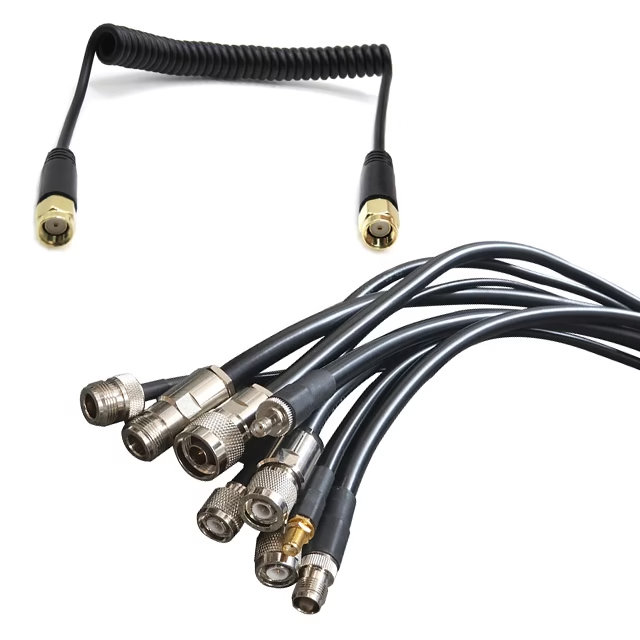
Radio-to-antenna and filter jumpers for RAN and small-cell equipment. We fit SMA, N-type, and 4.3-10 connectors and test VSWR.
DC power distribution harness
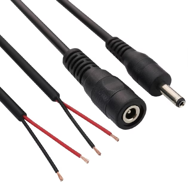
Connects the cabinet PDU to shelves and modules, with lug crimps pull-tested on high-current feeders.
Backplane and I/O interface cable harness
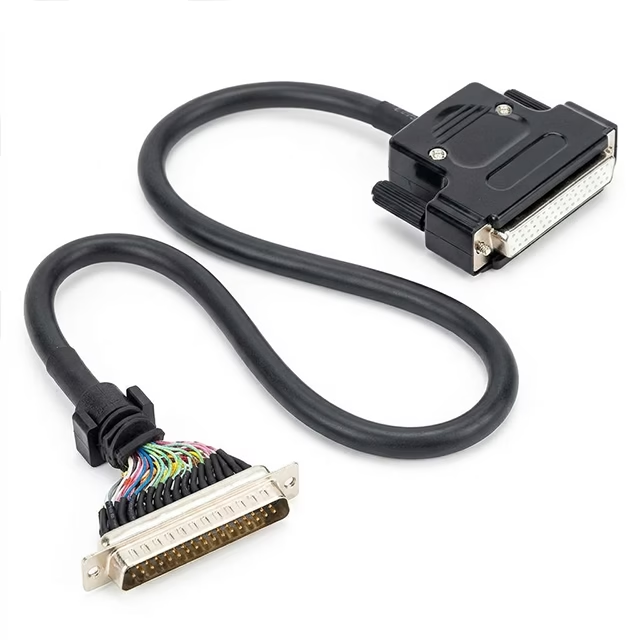
Links the chassis backplane to daughter cards and I/O panels.
Grounding and equipotential bonding harness
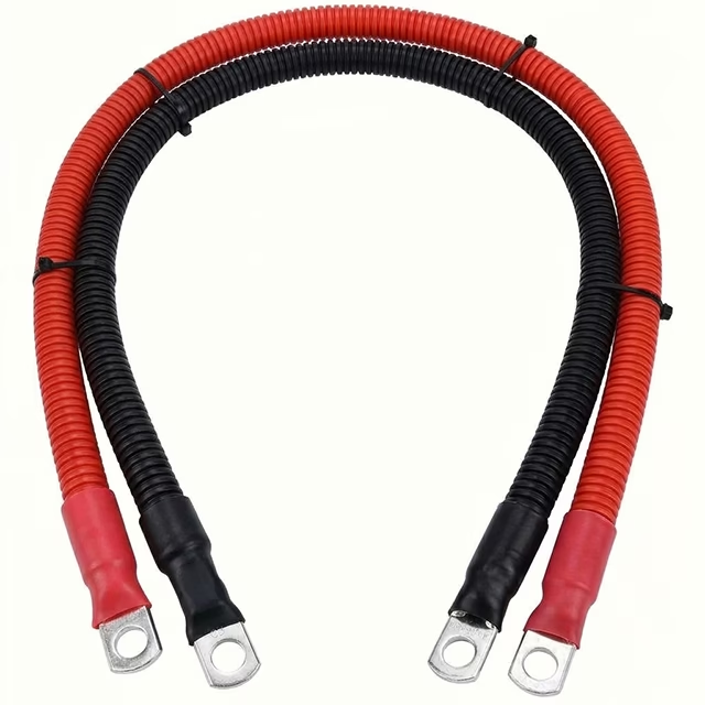
Provides rack and frame grounding for central office and outdoor cabinets.
Fiber breakout ODF pigtail assembly
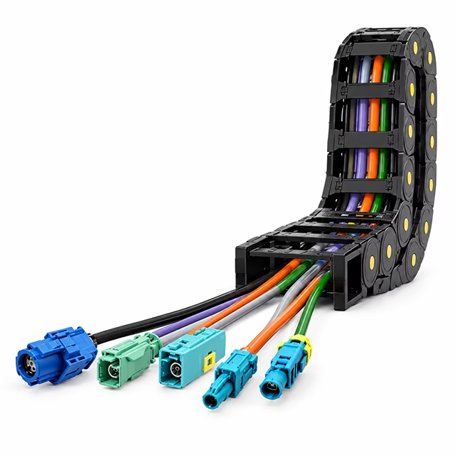
Fans out a fiber cable into connectorized pigtails for optical distribution frames.
BBU-to-RRU interconnect harness with fiber
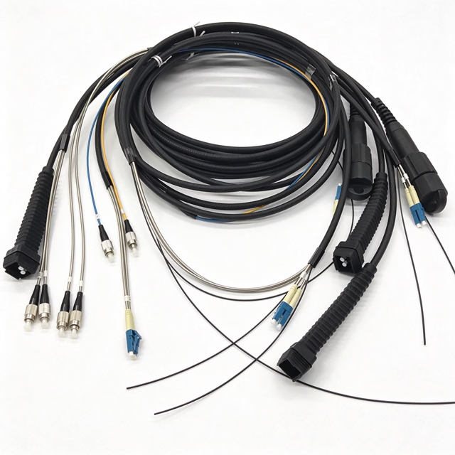
Combines fiber, DC power and alarm conductors in one run between the baseband unit and remote radio unit.
We also build EMI-shielded I/O harnesses, rack-to-rack trunks, and alarm monitoring harnesses.
Key specifications
| Item | What we offer |
|---|---|
| Conductors | Bare or tinned copper, stranded or solid |
| Wire size | 30 AWG signal wire up to heavy-gauge DC feeders |
| Insulation | PVC, PE, XLPE or PTFE, matched to plenum, riser or general-purpose use |
| Voltage rating | Up to 600 V, depending on wire and connector ratings |
| Connectors | JST, M8/M12/M16, D-sub, ring and spade lugs, RF (SMA, N-type, 4.3-10) |
| Termination | Crimp, solder or IDC, to IPC/WHMA-A-620 Class 2 or Class 3 |
| RF assemblies | VSWR-tested; low-PIM and phase-matched builds on request |
| Shielding | Braid or foil on EMI-sensitive lines |
| Temperature | −40 °C to +105 °C, depending on the jacket |
| Materials compliance | RoHS and REACH; UL-recognized materials on request |
| Prototype lead time | 5–15 business days |
| Production lead time | 2–4 weeks, depending on volume |
| MOQ | 10 pieces up to full production |
These specifications apply to our communications equipment wiring harnesses in general. However, we confirm the final values with you at drawing review.
How we keep communications equipment wiring harnesses consistent from sample to production
Drawing review and first article
First, we review your drawing. An engineer checks pinout, wire gauge, connector part numbers, bend radius and routing, and sends back questions before cutting any wire. Next, we build a first article for every program, whatever the order size. Once you approve it, it becomes the production reference.
In-process inspection and final testing
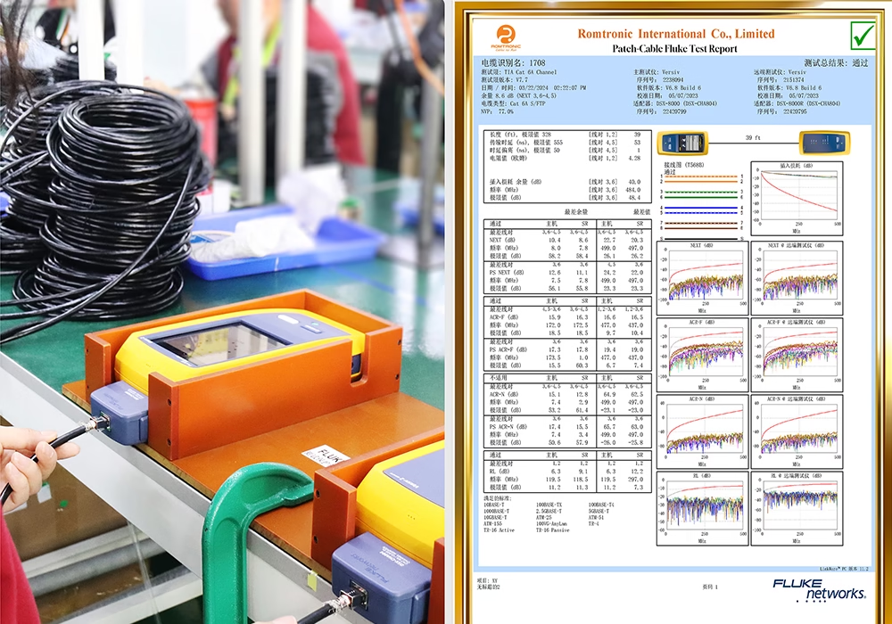
After that, we inspect each unit after termination, after assembly, and again at final QC. The table below shows what we test and how often. For more detail, see our testing and validation guide.
| Test | What it checks | Applied |
|---|---|---|
| Continuity | Correct pin-to-pin connection, no opens or shorts | 100% of units |
| Insulation resistance / hipot | Insulation integrity between conductors | 100% of units |
| Signal attenuation (insertion loss) | Signal loss along RF coax and signal lines across the specified frequency band, measured against your limit | As specified |
| TDR | Impedance and fault location on controlled-impedance lines | As specified |
| Crimp pull force | Mechanical strength of crimped terminals | Sample basis, or as specified |
| Bend cycle | Flex life of the cable and strain relief | Qualification, or as specified |
Engineering notes for telecom harnesses
−48 V DC feeders
Telecom equipment typically runs on a nominal −48 V DC supply, as defined by ETSI EN 300 132-2. For example, the Nokia 1830 ONE-m datasheet allows −40.5 V to −57 V at the input. Long or undersized feeders eat into that margin, so we check voltage drop at the drawing stage. You can also run your own numbers with our voltage drop calculator. We also pull-test lug crimps on feeders because a poor high-current joint runs hot.
RF jumpers
Passive intermodulation (PIM) depends heavily on workmanship. For example, Spinner’s 4.3-10 jumper data sheet lists a maximum IM3 figure for its own assembly, and the maker describes non-magnetic materials and fewer RF contact points as part of how it keeps PIM down. Therefore, we treat coupling torque and cleanliness as process steps. The 4.3-10 interface follows IEC 61169-54. If your system has a PIM limit, send us the target and test band, and we will confirm whether we can verify it.
Shielded I/O
Control and monitoring lines near RF or power conductors usually need shielding. However, the right shield termination depends on your grounding scheme, so we will agree on it with you during the drawing review.
Standards for communications equipment wiring harnesses
| Standard | How it applies |
|---|---|
| IPC/WHMA-A-620 (current revision F) | Workmanship and acceptance criteria for all harnesses. Class 2 covers sustained service; Class 3 covers critical or demanding use. |
| Telcordia GR-63-CORE / GR-1089-CORE | Physical, EMC, and electrical safety criteria for NEBS equipment. We build to your specified criteria, while the end equipment carries the certification. |
| ETSI EN 300 132-2 | −48 V DC power interface, our reference when we size feeders. |
| ANSI/TIA-568 | Structured cabling that our patch and cross-connect harnesses connect to. |
| NFPA 262 | Flame and smoke test for plenum-rated cable. Specify it if harnesses run through air-handling spaces. |
| UL 444 | Covers premises communications cable. It does not govern internal −48 V power or RF harnesses. |
| RoHS (EU 2011/65/EU) | For harnesses shipped to RoHS-regulated markets. |
We confirm which standards apply during drawing review, then include them in the build specification. You can also find our certificates on the certifications page. For more background, see our standards and compliance guide.
Where communications equipment wiring harnesses are used
Our communications equipment wiring harnesses go into these systems:
- Telecom and data centers: base station cabinets, RRU and BBU cabling, networking racks
- Central office racks, 5G small-cell and macro RAN equipment
- Broadcast and satellite ground equipment
- Industrial IoT gateways and rail signaling cabinets
Communications equipment wiring harness FAQ
Which IPC class should I specify?
Class 2 suits most telecom equipment that must run reliably for years. Class 3 fits equipment where failure is unacceptable, or the environment is severe. However, it costs more, so choose it only if your system needs it.
Can you copy an existing harness from a sample or an old drawing?
Yes. First, send the sample or drawing. Then we confirm the pinout, wire gauge, and connector part numbers with you before cutting any wire.
What is your minimum order?
We build as few as 10 pieces for low-volume, high-mix programs, and we scale up to full production volume.
Can you build communications equipment wiring harnesses to NEBS requirements?
We build to the GR-63-CORE and GR-1089-CORE criteria you give us. However, NEBS certification applies to the finished equipment, not to a harness alone.
Does UL 444 cover internal power or RF harnesses?
No. UL 444 covers premises communications cable. We build and test internal −48 V DC and RF harnesses to your equipment’s own electrical safety and EMC specifications.
Which connectors do you support?
We support JST, M8/M12/M16, D-sub, ring and spade lugs, and RF types including SMA, N-type, and 4.3-10. Ask us if yours isn’t listed.
What should I send for a quote?
Send a wire list or schematic, connector part numbers, wire specs, quantity, and required standards. If you have a reference sample, send that too. We then return a DFM review and quote within 12 hours.
Can you test PIM on RF jumpers?
Yes. We also test in the frequency bands and to the limits you specify.