


Wire harness design (also referred to as wiring harness design, electrical harness design, or cable harness design) is the process of turning a schematic into a physical, bundled, pre-routed assembly of wires, connectors, and terminals that delivers power and signal reliably within a defined space. A sound wire harness design process follows a repeatable sequence — requirements analysis, wiring harness drawing and schematic capture, component selection, a design-for-manufacturability (DFM) review, routing and bundling, termination, and validation testing — and is checked against workmanship references such as IPC/WHMA-A-620.
Skip or rush any one of these steps in an electrical wire harness design and the result is voltage drop, intermittent connections, or field failures that are expensive to trace back to their root cause.
This guide walks through how our engineering team approaches wiring and harness design on customer projects, including how we read and build a wire harness drawing, how we think about wire sizing, and the design mistakes we see most often in the field.
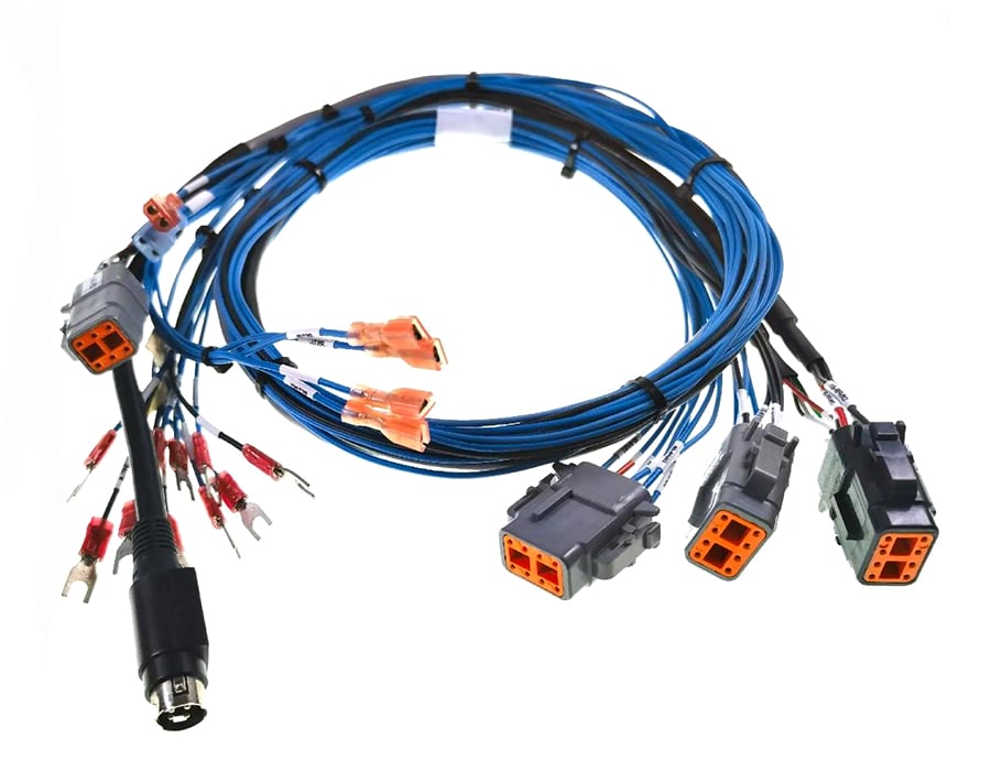
What Is a Wire Harness Assembly?
A wire harness — also called a wiring loom, cable harness, or wiring loom design output depending on the industry and region — groups multiple wires, connectors, and terminals into a single organized bundle, typically protected by sleeving, tape, or a molded jacket. Compared to loose point-to-point wiring, a properly engineered wire harness design reduces assembly time on the production line, standardizes routing so the same design behaves consistently in every unit, and simplifies troubleshooting because every wire has a known, documented path.
Wire harness designs and wiring loom designs are used wherever an OEM needs a repeatable, tested interconnect rather than hand-wired connections: automotive and EV powertrains, medical devices, industrial automation and robotics, telecom and data center equipment, and consumer/commercial appliances. The requirements differ significantly by industry — electrical harness design for a medical device prioritizes biocompatibility and patient-safety leakage-current limits, while automotive electrical wire harness design prioritizes vibration resistance and qualified automotive-grade components — but the underlying wiring harness design process below applies across all of them.
Related: What Is a Wire Harness? →
The 7-Step Wire Harness Design (DFM) Process
1. Requirements Analysis
Before any wire harness drawing is started, define the electrical envelope (voltage, continuous and peak current, signal type/frequency), the environmental envelope (operating temperature range, ingress protection needed, chemical/UV exposure, vibration profile), and the mechanical envelope (available routing space, minimum bend radius, connector keep-out zones). Most rework in wire harness designs traces back to a requirement that wasn’t captured at this stage.
2. Schematic Capture & Wiring Harness Drawing
Translate requirements into a wiring diagram and a formal wire harness drawing showing every connection point, wire-to-pin mapping, and shield/ground scheme. This wiring harness drawing becomes the single source of truth for BOM generation, test point definition, and later engineering-change tracking — it should be treated as a controlled document, not a sketch. In practice, a clear electrical wiring harness design starts and ends with a drawing that production, quality, and engineering can all read the same way.

3. Component & Wire Selection
Select conductor gauge, insulation material, connector series, and terminal type based on the requirements from Step 1. This is where design-for-manufacturability and electrical performance intersect: a connector with a tighter pitch may save space but increase the risk of assembly-induced shorts at production volume; an insulation material suited to one environment is not automatically suited to a hotter or harsher one. See the general wire gauge reference below as a starting point, and always confirm final sizing against the specific cable manufacturer’s datasheet and your project’s duty cycle.
4. DFM Review
Before finalizing any electrical harness design, review it against manufacturability criteria: Can the harness be built with standard tooling, or does it require custom fixtures that add cost and lead time? Are connector orientations keyed to prevent mis-mating on the line? Is there enough length tolerance built in to avoid stress on terminations? This is the step most templated “how-to” guides skip — and the step that determines whether a first production run ships on time.
5. Routing & Bundling
Route wires to avoid sharp edges, moving parts, and heat sources, respecting each cable’s minimum bend radius as specified by its manufacturer. Bundle related wires together with cable ties, spiral wrap, or braided sleeving, and keep high-current and sensitive signal circuits separated where practical to reduce electromagnetic interference (EMI) coupling. This is also the stage where a wiring loom design intended for a moving or flexing application (robotics, drag chains) needs a different bend-radius and strain-relief strategy than a fixed-installation harness.
6. Termination
Choose crimp, solder, or insulation-displacement termination based on the application’s vibration and thermal-cycling requirements. In vibration-prone applications, crimped connections are generally favored because they tend to be more resistant to the kind of fatigue cracking that can affect solder joints — though the right choice always depends on the specific application and should be confirmed against your quality requirements. Termination workmanship in any wire harness design should be built and inspected against IPC/WHMA-A-620, the industry-recognized workmanship reference for cable and wire harness assemblies.
7. Testing & Validation
Every wiring harness design should, at minimum, pass a continuity test and an insulation-resistance test before shipment. Depending on the application, additional verification may include crimp pull-testing, vibration or thermal-cycling testing, and sealing verification for ingress-protected connectors — the exact test plan should be defined jointly with your quality and reliability requirements rather than assumed from a generic checklist. A documented DFM process pays off here too: harness designs built with testability in mind (accessible test points, consistent pinout) are faster and cheaper to validate at scale.
Wire Gauge & Current-Carrying Capacity: General Reference
The ranges below reflect commonly used general engineering reference points for chassis-style wiring at moderate ambient temperatures — they are a starting point for discussion, not a substitute for a project-specific calculation. Actual safe current depends on insulation type, ambient temperature, bundling with other current-carrying conductors, run length, and the applicable standard for your industry and region. Always verify final sizing against the cable manufacturer’s datasheet and, where applicable, the standard your industry requires (e.g., automotive, aerospace, or appliance wiring standards).
| AWG | Relative Conductor Size | General Use Case |
|---|---|---|
| 24 AWG | Fine gauge | Low-current signal and control wiring |
| 22 AWG | Fine-to-medium gauge | Signal wiring, low-power control circuits |
| 20 AWG | Medium gauge | Light-duty power and control wiring |
| 18 AWG | Medium gauge | General-purpose power wiring |
| 16 AWG | Medium-heavy gauge | Higher-current power wiring |
| 14 AWG | Heavy gauge | Higher-power circuits, motor leads |
| 12 AWG | Heavy gauge | High-current power distribution |
For an exact ampacity and voltage-drop calculation based on your real current, run length, and ambient temperature, use our Wire Size Calculator, Ampacity Calculator, and Voltage Drop Calculator rather than relying on general tables. Need the AWG ↔ mm² conversion for a metric spec sheet? Use our AWG ↔ mm² Converter.
5 Common Design Mistakes (and How They Show Up as Field Failures)
| Design Mistake | Root Cause | How It Shows Up Later |
|---|---|---|
| Undersized conductors | Sizing to average current instead of peak/inrush current | Overheating, insulation degradation, voltage-drop-related device resets |
| Poor routing/bundling | No separation between high-current and signal circuits; wires routed across sharp edges without protection | EMI-induced signal errors; chafing-induced shorts after vibration exposure |
| Inconsistent termination quality | Crimp or solder process not controlled to a documented workmanship standard | Intermittent connections; field-return clusters traced back to a single termination batch |
| Skipping the DFM review | Wiring harness design finalized from a schematic-only perspective without manufacturing input | First-article rejects, tooling rework, missed production launch dates |
| Inadequate test coverage | Continuity-only testing with no insulation-resistance or pull-test data | Latent defects that pass initial test but fail in the field after thermal or vibration cycling |
For real (de-identified) failure case studies — connector oxidation, over-stress insulation cracking, and root-cause analysis of batch returns — see our Failure Analysis section of the Engineering Hub →
Standards & Compliance Checklist
| Standard / System | What It Generally Covers | When It Typically Applies |
|---|---|---|
| IPC/WHMA-A-620 | Workmanship requirements for terminating, crimping, and cable/wire harness assembly | Broadly used as a baseline workmanship reference across industries |
| UL wire and cable safety listings | Construction and safety ratings for appliance/equipment wiring materials | Products sold into the US market |
| ISO 13485 | Quality management system requirements for medical device manufacturing | Medical device wire harnesses |
| IATF 16949 | Automotive-industry quality management system requirements | Automotive/EV harnesses |
| IEC 60601 series | Medical electrical equipment safety requirements | Patient-connected medical device cabling |
| IEC 60068 series | Environmental testing methods (vibration, thermal cycling, humidity, etc.) | Industrial, automotive, and outdoor-rated harnesses |
The table above names standards families at a general level; specific clause numbers and test parameters vary by edition and application and should be confirmed against the current published standard and your customer’s specification before use in a design or quality document.
Romtronic operates under IATF 16949, ISO 13485, UL, and CE certification scope, with an independent in-house testing laboratory — see our Certifications and Independent Laboratory pages for current scope details. For a deeper breakdown of certification requirements by standard, visit the Standards & Compliance hub →
Free Design Tools
Use these calculators during the component-selection and routing steps of your wire harness design or wiring loom design:
- AWG Calculator
- Wire Size Calculator
- Ampacity Calculator
- Voltage Drop Calculator
- Minimum Bend Radius Calculator
- Wire Bundle Diameter Calculator
- Cable Weight Calculator
For the full DFM framework beyond this article — connector selection decision trees, length-tolerance design, and EMI/EMC design rules for electrical wire harness design — visit Engineering Hub – Design & DFM →
FAQ
What is the difference between a wire harness and a cable assembly?
The terms are often used interchangeably, and usage varies by industry. In general practice, “cable assembly” more often refers to a single cable terminated at both ends, while “wire harness” (or wiring loom) typically refers to a more complex, branched bundle of multiple wires and connectors routed through an assembly, such as one found in a vehicle or an industrial control panel.
What standard is generally used to judge wire harness workmanship quality?
IPC/WHMA-A-620, “Requirements and Acceptance for Cable and Wire Harness Assemblies,” is widely used across industries as a workmanship reference for crimping, soldering, wire preparation, and mechanical assembly. Specific acceptance criteria should always be confirmed against the current published edition.
How do I approach wire gauge selection for a new design?
Start from peak (not average) current draw, then consider ambient temperature, bundling with other current-carrying conductors, and run length, since voltage drop can matter as much as current rating on long runs. Use a project-specific calculation — such as our Wire Size Calculator — rather than a general reference table for a final design decision.
Why does a DFM review matter if the schematic already works electrically?
An electrically correct schematic can still be difficult or expensive to manufacture — for example, unkeyed connectors that allow mis-mating, insufficient length tolerance leading to termination stress, or a wire gauge too large for the chosen connector’s crimp barrel. A DFM review is meant to catch these issues before tooling and first-article builds, not after.
What testing should a wire harness pass before shipment?
At minimum, a continuity test and an insulation-resistance test. Depending on the application and customer specification, this may be extended to crimp pull-testing, vibration or thermal-cycling testing, and ingress-protection verification for sealed connectors — the specific test plan should be agreed with your supplier’s quality team rather than assumed.
Need a wire harness designed and built to your spec? Get a free engineering review and quote → Our team works from your BOM, drawing, or even a rough sketch, and responds within 12 hours.
.avif)
Sam Wu is the Marketing Manager at Romtronic, holding a degree in Mechatronics. With 12 years of experience in sales within the electronic wiring harness industry, he manages marketing efforts across Europe. An expert in cable assembly, wiring harnesses, and advanced connectivity solutions, Sam simplifies complex technologies, offering clear, actionable advice to help you confidently navigate your electrical projects.

