


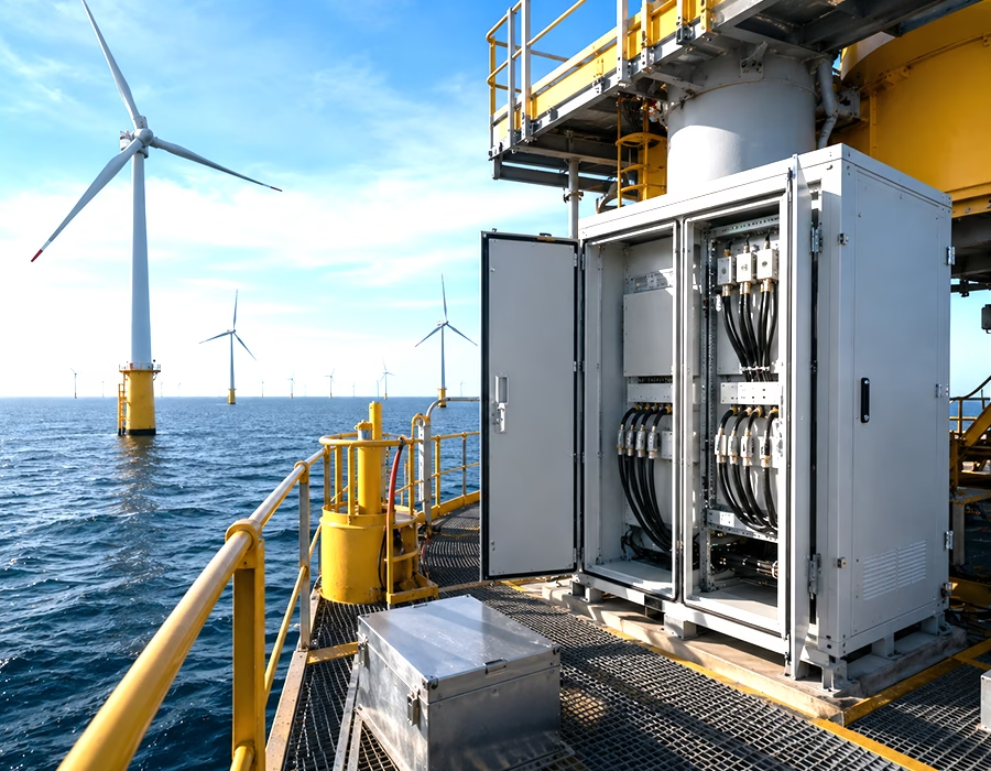
Decades of Service, Zero Access for a Field Fix
An offshore wind farm doesn’t get the luxury of a quick repair visit. A failed connector 40 kilometers out means a helicopter or a vessel charter before anyone even reaches the fault. That reality shapes every cable decision differently than an onshore project would.
We design and manufacture cable assemblies specifically for offshore wind farm applications, covering nacelle internal wiring, tower and transition piece cabling, inter-array jumpers, and condition monitoring harnesses. Our custom interconnects are built for decades of unattended service in one of the most corrosive environments in industrial engineering.
We bring 29 years of OEM/ODM experience to marine and renewable energy projects. As a high-mix, low-volume (HMLV) contract manufacturer, we handle everything from a single custom nacelle harness to a full turbine cabling kit, so project teams aren’t stuck coordinating parts across multiple vendors before installation.
- ISO 9001 factory validation. Every offshore wind farm assembly runs through our certified quality pipeline before it ships.
- Salt fog and corrosion tested. We test to ASTM B117/ISO 9227 salt spray standards, the same methodology we cover in our salt spray testing guide, on every material and finish we specify.
- IPC-A-620 Class 2/3 workmanship. Nacelle wiring, connector termination, and overmolded splice assembly all meet a documented, repeatable quality standard.
- Aligned with IEC 61400 design principles. Our cabling decisions account for the same environmental loading and reliability expectations that govern turbine design more broadly.
Technical Specifications and Manufacturing Matrix
| Parameter | Manufacturing Capability | Validation / Material Standards |
|---|---|---|
| Workmanship standard | IPC/WHMA-A-620 Class 2/3 | Certified IPC workmanship |
| Quality management | ISO 9001 factory certified | Third-party audited and documented |
| Conductor materials | Marine-grade tinned copper | Resists chloride-driven oxidation over decades |
| Connector plating | Nickel and gold-plated contacts | Minimizes galvanic corrosion at dissimilar-metal interfaces |
| Environmental sealing | IP67/IP68 overmolded connectors and splices | Rated for splash zone and full submersion exposure |
| Communication cabling | NMEA 2000, Modbus, CAN bus links | Shielded, per marine communication standards |
| Dynamic cable rating | High-flex jacketing for moving sections | Validated for repeated flex without conductor fatigue |
| Functional verification | Hi-pot, continuity, and salt fog aging tests | Full traceability per batch |
Six Offshore Wind Farm Cabling Types We Build For
We design, tool, and assemble interconnects across six core categories for offshore wind farm turbines:
- Nacelle internal wiring harnesses. Generator, gearbox, and control cabinet wiring inside the nacelle, built to handle constant vibration alongside salt-laden, humid air even before saltwater spray reaches the tower.
- Tower and transition piece power and control cabling. Vertical power runs and control cabling connect the nacelle down through the tower to the transition piece, where splash zone exposure is most severe.
- Inter-array cable jumpers. Turbine-to-turbine interconnects and topside terminations link the array’s electrical network, engineered for corrosion resistance at every connector interface.
- Condition monitoring system (CMS) sensor cabling. Vibration, temperature, and structural sensors feed data back through shielded cabling built to survive years of unattended exposure.
- Marine communication and navigation harnesses. NMEA 2000 and similar protocols link onboard systems and monitoring platforms, built to marine data cabling standards.
- Corrosion-resistant grounding and bonding kits. Bonding jumpers and grounding conductors protect against induced surge currents and galvanic buildup across dissimilar structural metals.
Two Failure Modes We Design Every Offshore Wind Harness Around
Galvanic Corrosion at Dissimilar-Metal Connector Interfaces
Offshore wind hardware routinely brings different metals into direct contact: aluminum housings, steel structures, copper conductors, all in a highly conductive saltwater atmosphere. Left unmanaged, that combination sets up a galvanic cell. The less noble metal corrodes away, sometimes years faster than either metal would alone.
We control this with nickel and gold-plated connector interfaces, isolation barriers between dissimilar metals, and material selections chosen specifically to minimize the galvanic potential between mating surfaces. It’s a more targeted fix than generic corrosion resistance, because it addresses the actual electrochemical mechanism instead of just the symptom.
Fatigue Failure in Dynamic Splash Zone Cable Sections
Not every offshore cable sits still. Sections that run through the splash zone or connect to floating or articulating structures see constant flexing from wave action and tidal movement, on top of the corrosion load. Standard marine cable rated for static installation can fatigue and crack at the conductor level long before its jacket shows any visible wear.
We address this with high-flex jacketing and conductor construction validated for repeated dynamic movement, not just static salt spray resistance. Getting the bend radius right in these dynamic sections matters as much as the material choice, and vibration-specific harness design principles apply directly to nacelle-mounted cabling as well.
Frequently Asked Questions
What causes galvanic corrosion in offshore wind cable connectors?
Galvanic corrosion happens when two dissimilar metals are in electrical contact within a conductive environment, like saltwater spray or humid marine air. The less noble metal corrodes preferentially, often much faster than it would in isolation. Nickel or gold-plated connector interfaces and proper metal isolation are the standard ways to prevent it.
Why does cable in the splash zone fail differently than cable higher up the tower?
Splash zone cabling deals with both corrosion exposure and constant mechanical flexing from wave and tidal action, while cabling higher in the tower mostly deals with corrosion and vibration alone. That combination of stresses causes fatigue cracking at the conductor level, which standard static-rated marine cable isn’t built to withstand.
What testing standard applies to offshore wind cable corrosion resistance?
ASTM B117 and ISO 9227 are the standard salt spray (salt fog) testing methods used to validate corrosion resistance in marine and offshore cable assemblies. Passing these tests demonstrates that a cable’s materials and plating can withstand sustained salt exposure without premature failure.
Do offshore wind farms use different cabling for communication versus power?
Yes. Power and control cabling typically uses heavier marine-grade conductors sized for the electrical load, while communication cabling for NMEA 2000, Modbus, or CAN bus networks uses shielded, lower-voltage constructions optimized for data integrity rather than power delivery.
Why is IEC 61400 relevant to cable assembly design, not just turbine structure?
IEC 61400 sets the environmental loading and reliability expectations that a wind turbine has to survive over its planned lifetime. Cabling is part of that reliability picture, since an internal wiring failure can take a turbine offline just as effectively as a structural issue can.
How long should offshore wind cable assemblies last without replacement?
Most offshore wind projects are designed for 20 to 25 years of service, and cabling is expected to match that timeline without field replacement, given how difficult and costly offshore access is. That’s why corrosion-resistant materials and connector plating matter far more here than in a comparable onshore installation.
Put Our Offshore Wind Cabling Team to Work
Offshore access is expensive and weather-dependent, which means a cable failure costs far more than the part itself. Whether you’re building out a new turbine platform, retrofitting condition monitoring across an existing array, or standardizing cabling for a multi-turbine project, we can help.
Upload your nacelle wiring diagrams, connector specs, or BOM directly to our Engineering Hub. Our team of 12 wiring engineers will run a full DFM audit and get a clean production quote back to you within 24 hours.
For our broader look at marine-grade cabling for offshore wind, our marine-grade cable assemblies for offshore wind farms piece is a good companion read.