The Engineering Hub page for Romtronic’s Common Failure Modes provides an engineering-oriented overview of common failure mechanisms in wire harnesses and cable assemblies, drawn from actual manufacturing experience, field input, and reliability engineering principles.
Most cable system failures are not random; they typically result from mechanical stress or electrical degradation induced by defined forces, environmental exposure, or manufacturing defects. This understanding of failure modes will help engineers troubleshoot, accurately design, validate, and manufacture more reliable interconnect systems.
Why Understanding Failure Modes Matters
Cable assemblies are essential in providing both structural and electrical support for electronic systems. Deficiencies in the quality of the terminated connection, routing, material composition, and environmental protection can lead to intermittent faults, signal loss, overheating, and, in some cases, catastrophic short circuits.
Engineering awareness of common failure modes enables teams to:
- Detect hidden risks early in the design phase
- Select materials and connector systems more effectively
- Control manufacturing variables and inspection criteria
- Reduce field failures, rework, and warranty exposure
- Support structured root cause analysis and corrective actions
Fundamental Failure Mechanisms
Across industries, most failures originate from a limited number of physical mechanisms:
- Fatigue – progressive damage under repeated bending, vibration, or micro-movement
- Overload – immediate failure when stress exceeds material limits
- Wear and abrasion – gradual insulation or plating loss due to friction
- Corrosion – chemical or electrochemical material degradation
- Thermal stress – cracking, softening, or loss of dielectric properties
- Creep – slow permanent deformation under continuous load
In complex systems, Common Mode Failures (CMF) are particularly critical because a single root cause can disable multiple conductors or redundant circuits.
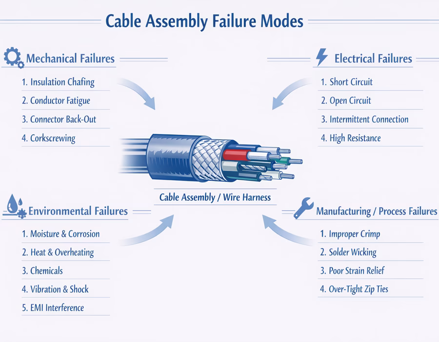
Major Cable & Wire Harness Failure Categories
Mechanical Failure Modes
Mechanical degradation is the most frequent “physical killer” of cable assemblies, often driven by routing, motion, or insufficient strain control.
Typical mechanical failures include:
- Insulation chafing from vibration against sharp edges, leading to exposed conductors and dead shorts
- Conductor fatigue and strand breakage at termination points or tight bend locations
- Connector back-out caused by incomplete seating, latch damage, or vibration
- Corkscrewing in dynamic cables, where internal conductors lose their lay and distort the jacket
- Strain relief failure allows loads to transfer directly into crimp or solder joints
These failures often progress invisibly before sudden functional loss occurs.
Electrical Failure Modes
Electrical failures are usually symptoms of underlying mechanical, environmental, or process issues.
Common electrical manifestations include:
- Short circuits from insulation breakdown or conductor contact
- Open circuits from fractured conductors or detached terminals
- Intermittent connections caused by contact fretting, micro-motion, or unstable crimps
- High resistance and voltage drop from poor crimp geometry or corrosion
- Shielding failure leading to EMI susceptibility and signal distortion
Intermittent faults are particularly difficult to diagnose and frequently indicate early-stage mechanical or surface degradation.
Manufacturing & Assembly-Induced Failures
Even robust designs can fail if manufacturing processes are not tightly controlled.
Common process-driven failures include:
- Improper crimping (under-crimp or over-crimp), reducing mechanical retention, and conductor life
- Conductor damage during stripping, introducing latent fatigue points
- Solder wicking, transforming flexible stranded wire into a rigid fracture zone
- Inconsistent wire tying, causing cold flow, insulation damage, or uncontrolled movement
- Inadequate overmolding or sealing, allowing stress transfer and moisture ingress
Process-induced defects are the dominant drivers of early-life failures.
Environmental Failure Modes
External conditions accelerate material aging and electrical degradation.
Typical environmental risks include:
- Moisture and salt exposure, leading to oxidation, leakage paths, and corrosion
- Extreme heat, embrittling insulation, and degrading dielectric strength
- Chemical contact, swelling, or dissolving jacket materials
- Vibration and shock, amplifying fatigue mechanisms
- EMI exposure disrupts unprotected signal circuits
Environmental failures often emerge after extended field operation.
Life-Cycle Perspective on Failures
Cable assembly failures generally follow a predictable reliability pattern:
- Early-life failures – manufacturing defects, setup errors, material inconsistencies
- Random failures – unpredictable events during stable service life
- Wear-out failures – fatigue, insulation aging, corrosion, and plating loss approaching end-of-life
Understanding where a failure occurs in the life cycle guides both troubleshooting strategy and preventive engineering actions.
How Engineers Detect Failure Modes
Effective failure identification relies on layered validation methods:
- Electrical testing for opens, shorts, and resistance drift
- Mechanical testing for pull force, flex endurance, and retention
- Environmental screening for accelerated aging behavior
- Visual, microsection, and cross-section analysis
- Functional testing under simulated application conditions
Combining these approaches enables early recognition of latent risks.
Engineering Strategies to Reduce Failure Risk
Most cable failures are preventable when engineering controls are applied upstream.
Key prevention pillars include:
- Design-for-manufacturability and routing evaluation
- Proper material and connector system selection
- Controlled termination process development
- Structured validation before production release
- In-process monitoring and traceable inspection
- Closed-loop failure analysis and corrective action
This engineering loop transforms failure data into reliability improvements.
Integration with Romtronic Engineering Systems
Failure mode knowledge supports all major Engineering Hub pillars:
- Design & DFM – eliminating known failure risks at concept stage
- Testing & Validation – verifying resistance to identified stress mechanisms
- Manufacturing Control – stabilizing processes to prevent defect creation
- Root Cause Analysis – accelerating corrective actions
- Standards & Compliance – aligning workmanship with accepted criteria
Get Started
If you are experiencing reliability challenges, preparing a new design for production, or seeking to reduce the risk of field failures, Romtronic’s engineering team provides structured support from failure identification through preventive engineering planning.
- Request a Quote – Contact Romtronic for custom cable assemblies or custom wiring harness solutions.
- Contact Engineers – Get technical guidance from our experienced engineering team.
- Our Product Brochure – Access Romtronic’s product brochure for all cable and harness solutions.