Radio frequency (RF) cable assemblies may look simple, but they are critical building blocks in wireless communication, aerospace, test, and defense systems. A well-designed RF assembly ensures reliable signal transmission with low loss, minimal reflections, and strong environmental durability. In this guide, we’ll break down the fundamentals—from history and structure to connector types, performance, testing, and future trends.
What Are RF Cable Assemblies?
An RF cable assembly is a coaxial cable pre-terminated with connectors on both ends, designed to carry high-frequency signals with minimal loss. It consists of:
- Center conductor (usually copper)
- Dielectric insulator (PTFE, PE, or foam)
- Shielding layer (braided copper or foil for EMI protection)
- Outer jacket (PVC, PE, or fluoropolymer for protection)
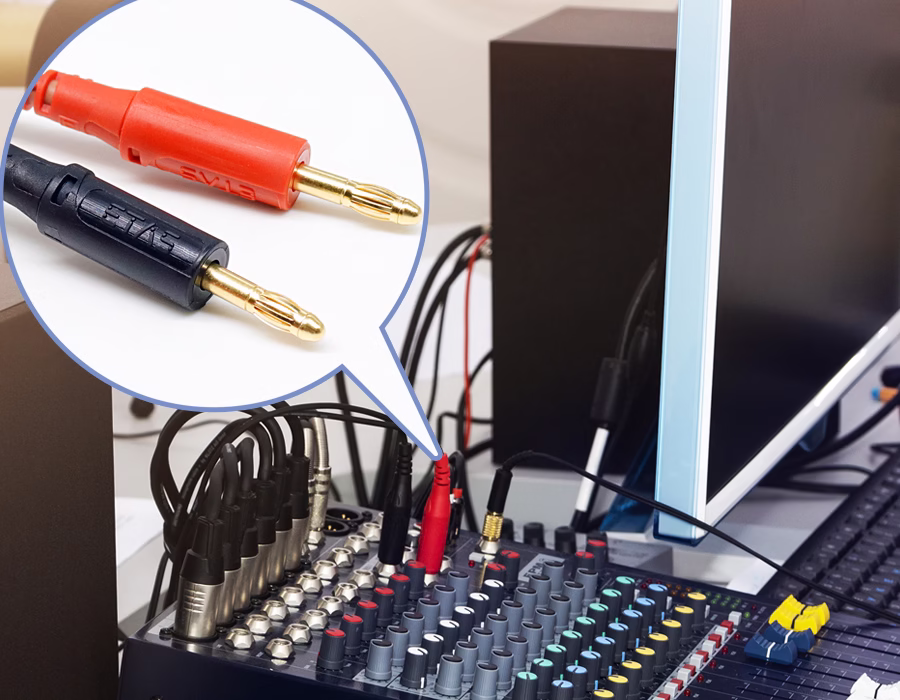
- Connectors (SMA, BNC, N-type, etc.)
RF assemblies are used to connect antennas, radios, test instruments, and virtually any device that handles signals from MHz up into the GHz range.
A Brief History of RF Cable Assemblies
Early Development of Coaxial Cables
Coaxial cables were developed in the early 20th century to enable long-distance transmission without interference. During World War II, the U.S. military standardized “RG” cables for radar and radio systems.
The Birth of Classic Connectors
- BNC (Bayonet Neill–Concelman): Introduced in 1944 by U.S. Navy engineers, offering a quick-lock 50 Ω connection for rugged RF use.
- TNC (Threaded Neill–Concelman): A threaded version from the 1950s, offering better microwave performance and weather resistance.
Expansion into the Microwave and 5G Era
Later, SMA connectors extended frequency performance into the 18–26.5 GHz range, and precision variants, such as 2.92 mm and 2.4 mm, pushed beyond 40–50 GHz. Today, with the advent of 5G and emerging 6G networks, RF assemblies must handle frequencies approaching 100 GHz while maintaining lightweight and reliable designs.
Market Demand and Applications
The RF cable assembly market is experiencing significant growth. In 2024, global revenues were about $33 billion, and forecasts predict $50+ billion by 2030 (≈7–8% CAGR).
Telecom and 5G Infrastructure
5G networks require ultra-low-loss cables and phase-stable assemblies for massive MIMO and mmWave small cells.
Aerospace and Defense
Satellite systems, radar, avionics, and secure communication all rely on high-performance assemblies. Semi-rigid and ruggedized cables are standard here.
Medical, IoT, and Test Equipment
MRI imaging, IoT sensors, and precision lab instruments require assemblies that strike a balance between compact size, low noise, and repeatability.
✏️ Looking for robust and future-ready cable assemblies for smart infrastructure?
Romtronic provides fully customizable wiring harnesses and modular cable assemblies that integrate sensors, fiber optics, and durable enclosures for seamless smart city deployment.
📩 Contact our engineering team for tailored solutions →
Future Trends in RF Cable Assemblies
- 5G/6G mmWave: Demand for stable performance into 24–100 GHz.
- Miniaturization: Growth of micro-connectors like SMPM and SMPS.
- Lightweight Materials: Essential for UAVs, satellites, and aerospace.
- High-Density Interconnects: More connectors in less space, without crosstalk.
- Sustainability: RoHS/REACH compliance and recyclable jackets are becoming the norm.
Structure of Coaxial RF Cables
A coaxial RF cable has a simple but effective structure:
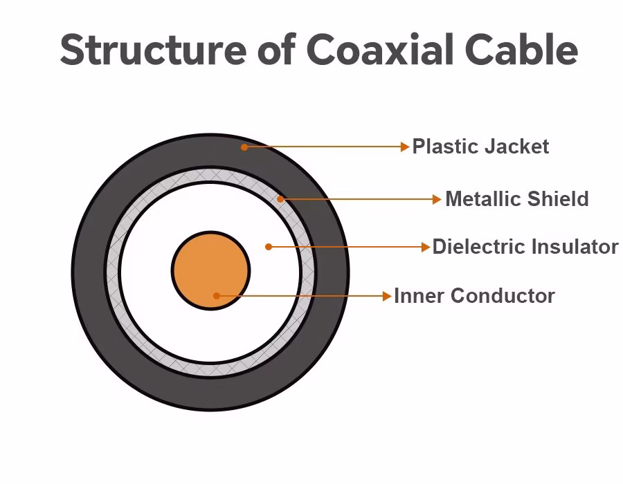
- Inner Conductor: Solid or stranded copper wire
- Dielectric Insulator: Sets impedance (commonly 50 Ω or 75 Ω)
- Metallic Shield: Braid or foil providing >90% coverage
- Plastic Jacket: Protective plastic layer
Cable Types
| Type | Frequency Range | Flexibility | Typical Use Cases |
|---|---|---|---|
| Flexible coax | DC–several GHz | High | General RF links, test benches |
| Semi-rigid | Up to 40+ GHz | Low | Aerospace, radar, high-precision |
| Corrugated | Up to 70 GHz | Medium | Telecom, satellite backhaul |
| Twinax/Triax | <100 MHz | Medium | Differential signals, video, sensors |
RF Connector Types
RF cable assemblies terminate in connectors. Four of the most common:
SMA
- Threaded 50 Ω, up to 18 GHz (26.5 GHz for precision versions)
- Used in Wi-Fi, microwave systems, and test gear
- Requires torque tools, ~500 mating cycles
BNC
- Bayonet coupling, 50 Ω or 75 Ω, up to ~2 GHz
- Quick connect/disconnect, common in labs and video
- Limited high-frequency use, not weatherproof
TNC
- Threaded version of BNC, 50 Ω, up to ~12 GHz
- Rugged, weather-resistant, used in telecom and outdoor gear
N-Type
- Larger threaded connector, 50/75 Ω, up to 11–18 GHz
- Handles high power, outdoor use (base stations, radar)
Connector Comparison Table
| Connector | Coupling | Impedance | Frequency | Applications | Pros | Cons |
|---|---|---|---|---|---|---|
| SMA | Threaded | 50 Ω | to 18–26 GHz | Microwave, Wi-Fi, test | Compact, reliable | Limited life cycles |
| BNC | Bayonet | 50/75 Ω | to 2 GHz | Labs, video | Quick connect | Not weatherproof |
| TNC | Threaded | 50 Ω | to 12 GHz | Outdoor, telecom | Rugged, higher freq than BNC | Larger, slower connect |
| N-Type | Threaded | 50/75 Ω | to 11–18 GHz | Base stations, radar | High power, durable | Bulky |
Key Performance Metrics
- Impedance Matching: 50 Ω for RF/microwave, 75 Ω for broadcast. Mixing causes VSWR.
- Insertion Loss: Increases with frequency and length, making it critical for 5G and radar applications.
- Return Loss / VSWR: Lower is better; VSWR <1.2 is high performance.
- Power Handling: Ranges from watts (SMA) to kilowatts (7/16 DIN).
- Shielding Effectiveness: Double shielded coax achieves >100 dB isolation.
- Phase Stability: Essential in phased arrays and interferometry.
Mechanical and Environmental Factors
- Flexibility and Bend Radius: Over-bending ruins impedance.
- Durability: SMA rated for ~500 cycles, N-type rated for ~1000 cycles.
- Temperature Range: −55 °C to +125 °C, common with PTFE dielectric.
- Moisture Resistance: Outdoor connectors use O-rings and plating.
- Vibration/Shock: Aerospace cables meet MIL-STD-810 requirements.
Testing and Quality Assurance
Manufacturers use:
- Continuity and Insulation Tests (high resistance between shield and conductor)
- VNA Measurements (insertion loss, VSWR, phase)
- High-Voltage Breakdown Tests (1 kV typical)
- Mechanical Stress Testing (bend, vibration, mating cycles)
- Standards Compliance (MIL-STD-348 for connectors, MIL-DTL-17 for coax, IPC/WHMA-620 for cable assemblies)
Choosing the Right RF Cable Assembly
- Match impedance (50 or 75 Ω).
- Check the frequency range (e.g., SMA for 18 GHz, precision for frequencies above 40 GHz).
- Select the connector type based on the environment (BNC for lab, TNC/N-type for outdoor use).
- Consider mechanical needs (flexibility, bend radius, weight).
- Ensure environmental fit (temperature, moisture, EMI compliance).
Leading Manufacturers
Key players include Amphenol, TE Connectivity, HUBER+SUHNER, Rosenberger, Radiall, Times Microwave, Pasternack, Samtec, and Carlisle Interconnect. Many offer both catalog assemblies and custom builds. Specialized products include Samtec’s phase-stable Nitrowave cables and Huber+Suhner’s SUCOFLEX microwave series.
✏️ Need precision RF cable assemblies for aerospace, defense, or 5G applications?
Romtronic delivers high-frequency, phase-stable assemblies engineered to meet strict industry standards—whether for satellites, radar, or next-gen telecom networks.
🚀 Request a custom quote from our RF specialists today →
FAQ
Q1: What’s the difference between 50 Ω and 75 Ω RF cables?
50 Ω is the standard for RF and telecom applications; 75 Ω is commonly used in video and broadcast applications. Mixing increases VSWR.
Q2: Which connector is best for high frequencies?
SMA works up to 18 GHz. For frequencies above 26 GHz, use precision connectors such as 2.92 mm, 2.4 mm, or 1.85 mm.
Q3: How do I test if a cable assembly is still good?
Measure VSWR and insertion loss with a VNA. A sudden increase indicates damage.
Q4: Can adapters be used between connectors?
Yes, but each adds loss and reflection. For critical use, order a direct assembly.
Q5: How long do RF connectors last?
Typically, 500–1000 mating cycles, depending on type and handling.
Conclusion
RF cable assemblies may seem like small components, but they play a crucial role in enabling modern communication. From coaxial structure to connector choice, performance metrics, and testing standards, every detail impacts reliability. As 5G expands and 6G looms, assemblies must strike a balance between high frequency, durability, and miniaturization. By understanding the fundamentals and making informed choices, engineers and enthusiasts alike can ensure their systems achieve optimal performance.
.avif)
Sam Wu is the Marketing Manager at Romtronic, holding a degree in Mechatronics. With 12 years of experience in sales within the electronic wiring harness industry, he manages marketing efforts across Europe. An expert in cable assembly, wiring harnesses, and advanced connectivity solutions, Sam simplifies complex technologies, offering clear, actionable advice to help you confidently navigate your electrical projects.