An IDC cable is a flat ribbon or discrete-wire cable terminated with an insulation-displacement connector — a connector that pierces a wire’s insulation with a metal blade to make contact, instead of requiring you to strip and crimp or solder the wire first. Because the process takes only a fraction of a second per contact, IDC termination is the fastest mass-termination method available for flat cable. That speed is exactly why manufacturers almost always sell ribbon cable and IDC connectors as a matched pair.

How Does an IDC Cable Connector Work?
IDC connectors are very clever. Rather than stripping the wire, a narrow, V-shaped metal blade inside the connector body pierces straight through the insulation and wedges against the bare copper underneath. Technicians sometimes call this “cold-welding,” since the piercing action forms a gas-tight, metal-to-metal connection without soldering or any specialized tools. Because the press drives the entire ribbon into the connector in one stroke, this method remains the fastest way to mass-terminate multi-conductor flat cable.

Two main parts make up an IDC connector:
- Connector body — usually plastic or metal, housing the sharp teeth or blades that cut through the wire’s insulation.
- Contacts (pins) — shaped to grip the individual conductor once the insulation displaces, maintaining a stable, low-resistance connection over time.
Pitch — the center-to-center spacing between contacts — is the one design variable that determines whether a termination performs reliably. Get the pitch, conductor gauge, or insulation diameter wrong for the connector, and the termination will be unreliable no matter how good the press tool is.
IDC Cable Connector Pitch, Current, and Voltage Ratings
Four pitch sizes cover almost every IDC cable application in cable assembly work today. We compiled the figures below from common connector manufacturer datasheets (JST, TE Connectivity, Molex, Würth Elektronik), so always confirm the exact numbers against the datasheet for your specific part number, since current rating shifts with contact plating, AWG, and ambient temperature. For reference on choosing the right conductor size for a given current, see our wire gauge selection guide.
| Pitch | Typical Current Rating | Typical Voltage Rating | Typical Operating Temp. | Typical Use Case |
|---|---|---|---|---|
| 1.0 mm | 0.7–1.8 A (varies by AWG and series) | 50 V AC/DC | −25 °C to +85 °C | Compact wire-to-board connections in cameras, handheld devices, and space-constrained consumer electronics |
| 1.27 mm (0.05″) | 1.0–1.4 A | 100–250 V AC/DC | −40 °C to +105 °C | ARM SWD/JTAG debug headers, industrial I/O, medical device internal wiring |
| 2.0 mm | ~1.0 A | 250 V AC/DC | −40 °C to +105 °C | Industrial control systems, compact I/O modules, communication and test equipment |
| 2.54 mm (0.1″) | 1.0–3 A per contact (AWG-dependent) | 150–300 V AC/DC | −55 °C to +105 °C | Legacy ribbon cable (IDE/floppy-style headers), prototyping, general-purpose wire-to-board |
As pitch increases, current capacity and mechanical durability go up, but so does the footprint. For example, a two-row, 2.54 mm-pitch connector requires ribbon cable with a 1.27 mm conductor pitch, because the staggered contact rows split that spacing in half. Matching cable pitch to connector pitch correctly is therefore one of the more common, and easily avoidable, errors in custom cable assembly design. Meanwhile, our production team inspects every termination against the IPC/WHMA-A-620 workmanship standard’s acceptance criteria.
Why Choose IDC Cables?
- Quick, tool-less assembly — no wire stripping, soldering, or specialized tools required. Simply press the connector into place and it’s ready to use, saving both time and labor cost.
- Cost-effective at volume — faster assembly with simpler tooling makes IDC a budget-friendly choice for high-mix, high-volume ribbon cable programs.
- Reliable connection — the piercing action creates a gas-tight, vibration-resistant connection that holds up over the life of the product.
- Versatile — manufacturers offer these connectors across the pitch range above, with options like locking clips and strain relief for different mechanical environments.
| Benefit | Description |
|---|---|
| Fast assembly | No soldering or wire stripping required |
| Cost-effective | Reduces time and labor costs |
| Reliable connections | Gas-tight, vibration-resistant termination |
| Versatile | Available in multiple pitches and configurations |
Where Are IDC Cables Used?
Overall, IDC cables show up anywhere a design needs to terminate many parallel conductors quickly and consistently:
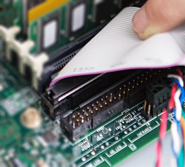
- Computers — internal connections between drives, motherboards, and front-panel headers.
- Medical devices — precision, reliability-critical internal wiring.
- Telecommunications — routers, switches, and other network equipment.
- Automotive and industrial — wiring harnesses and control system interconnects.
IDC Cable Advantages and Limitations to Design Around
This termination method isn’t the right choice everywhere. It performs best with solid or fine-strand conductors within the gauge range the manufacturer qualified the connector for, and it’s more sensitive to vibration and repeated flexing at the termination point than a crimped, housed connector, unless the design adds proper strain relief. Consequently, pairing an IDC connector with the wrong AWG or an over-jacketed cable is a frequent root cause of high contact resistance and early field failures. Our Failure Analysis team sees this most often when a design carries over from a low-vibration desktop application into an industrial or mobile environment without re-evaluating the termination method.
For background on the broader family of insulation-displacement technology, see Wikipedia’s overview of insulation-displacement connectors.
Assembling the Connector, Step by Step
Making an IDC cable assembly requires only a few tools:
- Gather materials — ribbon cable, IDC connectors matched to that cable’s pitch, and an IDC press tool.
- Align the connectors — line up the connector contacts with the cable conductors, and confirm correct orientation and polarity.
- Press the connectors — the press drives the blades through the insulation in a single stroke, forming the termination.
A single prototype connection needs no specialized skill. Production volume, however, is a different story: consistent, defect-free termination depends on press calibration, tooling maintenance, and incoming cable/connector quality control — which is where a dedicated cable assembly manufacturer earns its keep.
Romtronic: Your Go-To IDC Cable Manufacturer
At Romtronic, we specialize in custom IDC cable assemblies across all four common pitches. We run in-house IDC presses, perform continuity and hi-pot electrical testing on every production run, and apply IPC/WHMA-A-620 workmanship standards to every build. So whether you’re specifying a compact 1.0 mm-pitch harness for a handheld device or a rugged 2.54 mm ribbon assembly for industrial control gear, our engineering team can help validate pitch, conductor gauge, and current requirements before tooling starts.
Key Takeaways
In short, IDC cables deliver fast, reliable, cost-effective wire termination without stripping, soldering, or specialized tools, provided you match the pitch, gauge, and connector correctly for the application. Whether you’re designing a new product or upgrading an existing one, understanding these fundamentals up front avoids the most common — and costly — design mistakes.
If you’re looking for customized IDC cable assemblies, Romtronic is here to help. Request a quote with your BOM, drawing, or even just photos, and our engineers will provide DFM feedback within 12 hours.
Frequently Asked Questions
A: IDC stands for insulation displacement connector (or insulation displacement contact) — a termination method that pierces wire insulation to make contact rather than requiring you to strip the wire first.
A: Crimp termination strips the wire and mechanically compresses a separate metal terminal around the bare conductor. By contrast, IDC termination skips the strip step entirely: the connector’s contact blade cuts through the insulation itself when you press the wire into its slot. As a result, IDC is faster for multi-conductor ribbon cable, while crimp terminals generally hold up better under vibration and repeated flexing.
A: Manufacturers rate most IDC connectors for a limited number of mating cycles (commonly 20–50 for lower-cost styles), and you can’t re-terminate the connection onto a fresh section of wire without cutting and re-stripping the cable end. So for frequent disconnect/reconnect applications, choose a connector series that the manufacturer explicitly rates for higher mating-cycle counts.
A: Yes — insulation displacement termination depends on the wire sitting precisely in the contact slot, so cable pitch, conductor gauge, and insulation outer diameter all need to match what the manufacturer qualified the connector series for. Mixing pitches or gauges, in fact, is one of the most common causes of intermittent contact resistance in the field.
.avif)
Sam Wu is the Marketing Manager at Romtronic, holding a degree in Mechatronics. With 12 years of experience in sales within the electronic wiring harness industry, he manages marketing efforts across Europe. An expert in cable assembly, wiring harnesses, and advanced connectivity solutions, Sam simplifies complex technologies, offering clear, actionable advice to help you confidently navigate your electrical projects.