If you’ve ever seen an AS-i node going offline immediately after installation, it’s likely due to a poorly installed piercing connector. AS-Interface (AS-i) systems are easy to use, quick, and dependable—but only if you handle their flat cables and piercing connectors with the care and consideration they require.
This article outlines the dos and don’ts of installing AS-i flat cables, including how to select the best components, avoid common issues, and maintain the stability of your automation network for years to come.
How AS-i Piercing Connectors Work
Power and data can be quickly tapped from the flat wire using AS-i piercing connectors, often known as insulation displacement connectors, or IDC. No soldering or stripping is required; position the clamp over the cable and tighten the screw.
Metal pins inside the connector directly touch the copper conductors after puncturing the insulation. Polarity errors are nearly impossible because each clamp is keyed to suit the AS-i cable only in one direction. The connection is IP65/IP67 rated, gas-tight, and vibration-proof when appropriately connected.
💡 Tip: The above is the operation video of connecting AS-Interface flat cable, Always make sure the cable sits flat and centered under the clamp before tightening. A slight misalignment can cause intermittent contact later on.
Choosing the Right Cable and Connector
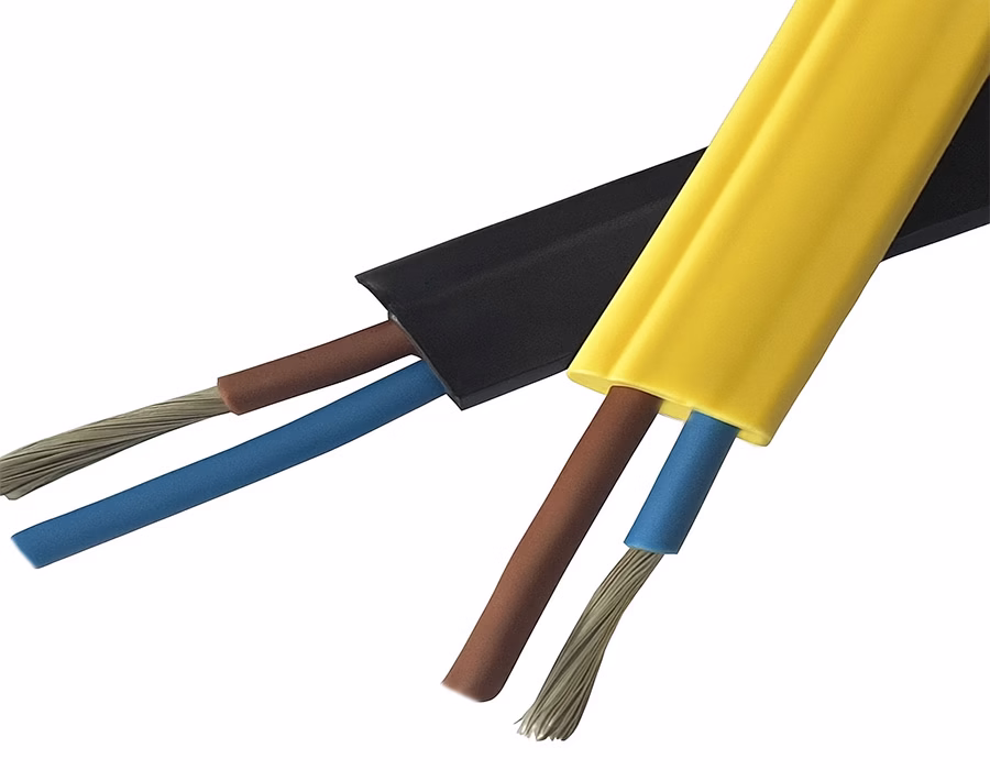
Use official AS-Interface flat cables, which are usually black for supplemental 24 V power and yellow for data/power.
Reversed connections are prevented by the unique design of the yellow cable. For equipment such as motors or valve manifolds, the black version provides additional current.
Keep these in mind:
- Use AS-i certified connectors and splitters rated for up to 8 A and 30 V DC.
- For long runs, check voltage drop—especially above 2 A load or 100 m length.
- Avoid running AS-i cables parallel to high-voltage or noisy motor cables. Maintain a spacing of at least 10–20 cm.
Installation Tips: The Do’s That Matter Most
- Align Carefully – Match the cable’s keyed shape to the connector before tightening.
- Use the Right Torque – Tighten with a socket wrench to about 1.6–2.0 Nm. Too loose = bad contact; too tight = cracked housing.
- Keep Conductors Straight – Ensure both copper strips are centered under the piercing pins.
- Inspect Before Clamping – Don’t reuse damaged or previously pierced cable sections.
- Test Every Connection – After installation, check voltage and continuity, and confirm that the module LEDs display power and communication.
⚙️ Pro move: If you see blinking red/yellow lights on the AS-i master, recheck the last connector you installed—it’s often the culprit.
Do’s and Don’ts Table
| ✅ Do’s | ❌ Don’ts |
|---|---|
| Use official AS-i flat cable (yellow or black). | Don’t use generic round wire—it won’t align or seal properly. |
| Tighten to the specified torque (~1.6–2 Nm). | Don’t overtighten or use pliers. |
| Keep cable flat and clean before piercing. | Don’t clamp over dirt, oil, or damaged insulation. |
| Check polarity markings before locking clamp. | Don’t flip the connector or ignore keying. |
| Use IP67 connectors for wet areas. | Don’t leave open clamps exposed to moisture. |
| Test communication after each tap. | Don’t skip testing or exceed 100 m without termination. |
Troubleshooting: When Things Go Wrong
If your AS-i network starts acting up—devices disconnecting, flickering LEDs, or communication drops—suspect the piercing connectors first.
Check these common culprits:
- Loose or corroded clamps: Tighten or replace them with new, non-rusty ones.
- Damaged cable: Cuts or kinks can break conductors under the clamp.
- Voltage drop: Measure the bus voltage at the last node (it should be ≥18.5 V). Add a repeater or thicker cable if needed.
- Unseated cover: Make sure the clamp body is flush and fully locked.
🔍 Pro tip: It’s faster to replace a questionable clamp than to chase down intermittent faults for hours.
Quick Recap Before You Go
The majority of AS-i communication problems ultimately stem from minor mechanical errors, such as misaligned pins, bent insulation, or incorrect torque.
Your AS-Interface network will thank you for years of reliable, low-maintenance performance if you follow the fundamental dos and avoid the don’ts.
FAQ
Not recommended. Once the pins pierce the insulation, their shape deforms. Always use a new connector for reliable contact.
Most clamps use about 1.6–2.0 Nm, or come with a break-off head that snaps when the correct torque is reached.
That usually means poor contact or voltage drop. Check nearby clamps and re-torque them.
Keep each segment under 100 m without a repeater. Longer runs require termination or a bus extender.
Yes, but protect yellow cables from UV exposure; use the black, UV-stable version instead.
Conclusion
In industrial automation, minor features have a significant impact. Smoother performance, cleaner diagnostics, and fewer downtimes are all results of an AS-i piercing connector that is placed correctly.
Romtronic’s carefully designed custom cable assemblies can help you create a robust and effective network from the very first connection, whether you’re updating existing lines or establishing a new AS-Interface configuration.
.avif)
Sam Wu is the Marketing Manager at Romtronic, holding a degree in Mechatronics. With 12 years of experience in sales within the electronic wiring harness industry, he manages marketing efforts across Europe. An expert in cable assembly, wiring harnesses, and advanced connectivity solutions, Sam simplifies complex technologies, offering clear, actionable advice to help you confidently navigate your electrical projects.