Choosing the right connector is not just a parts decision; it is a reliability decision. Selecting the wrong connector can lead to intermittent signals, corrosion, overheating, and costly field fixes. This guide provides engineers and procurement teams with a practical, technically accurate process for selecting a connector that meets electrical, mechanical, environmental, and compliance requirements.

Why connector choice matters
Connectors are the interface between your harness and the system. A good connector provides reliable contact, proper sealing, controllable mating force, and predictable lifetime. A poor connector will require more servicing, increase warranty risk, and may compromise safety. Start choosing connectors as early as possible (concept and DFx), because it is easier to change before a design has been finalized.
Step 1 — Define the operating environment (this drives many choices)
Answer these questions first:
- Indoor or outdoor? Generally, outdoor kits will require either an IP67/IP68-rated connector or a completely sealed automotive plug.
- Temperature range? Provide expected minimum and maximum ambient temperature, and any localized high-temperature areas (like engine bay). Specify numbers, not an educated guess.
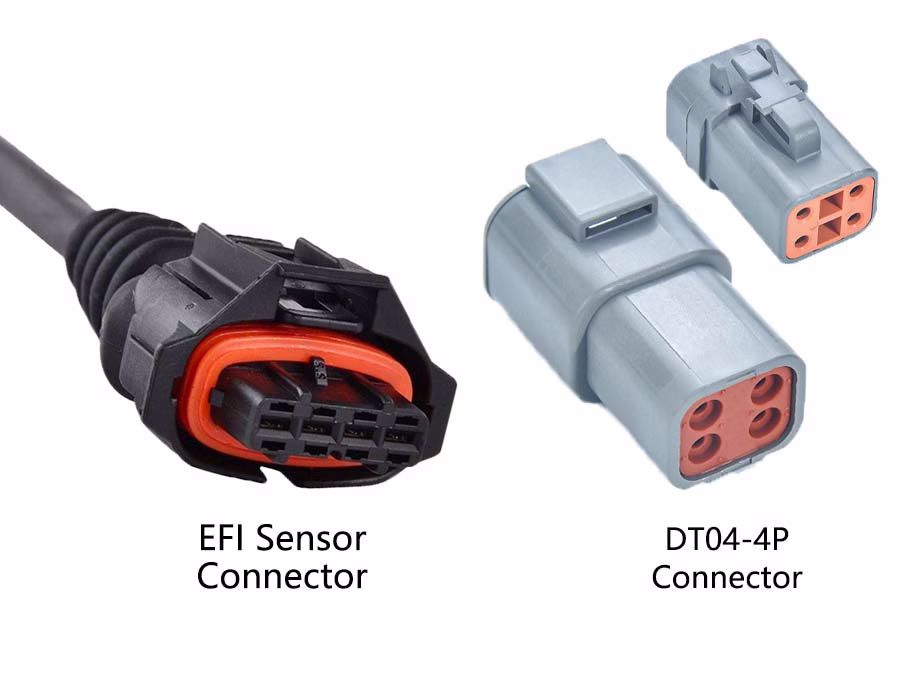
- Vibration/shock? If vibration or shock is present, select a connector with screw-lock, bayonet, or Deutsch compatibility, and ensure it is rated for vibration.
- Chemical/oil exposure? Please specify whether chemicals or oils are to be exposed to or come into contact with the wire connection so that we can confirm the compatibility of the plastics and PTFE seals.
- Ingress and cleaning (pressure wash, steam, sterilization) will affect gasket and material selection.
All of these factors determine the seals, the housing material, whether plating is needed, and whether a standard or heavy-duty connector is required.
Step 2 — Match electrical requirements
Be very clear with your electrical specifications:
- Voltage & peak voltage (V)
- Continuous and inrush current (A) per pin and total current per connector
- Signal type: power, analog signal, CAN/LIN, Ethernet, USB/DP, RF, or mixed
- High-speed specs: required impedance control or shielding for USB 3.x, DisplayPort, LVDS, Automotive Ethernet (100BASE-T1/1000BASE-T1)
- Derating rules: apply safety margin—select a connector rated above your max expected load.
For mixed-signal connectors, also review any listed crosstalk and ground-layout guidance in the manufacturer’s datasheet.
Step 3 — Evaluate mechanical and dimensional constraints
Consider:
- Space envelope and panel cutout — pick form factor accordingly (micro, mini, circular).
- Pin count & arrangement — ensure room for future expansions; avoid cramming many small pins if power pins are needed.
- Mating cycles — specify expected number of disconnects (e.g., 100, 500, 1,000 cycles).
- Mating force & retention — does the operator connect/disconnect frequently? Choose latch vs screw-lock accordingly.
- Strain relief and routing — require overmolding or boots for flex zones; specify bend radius.
For molding solutions, see: Cable Overmolding Guide
Step 4 — Sealing, materials & plating
- Seals & IP rating: IP54, IP67, and IP69K are not interchangeable—define the test (immersion depth/time, high-pressure wash) you need.
- Housing materials: polyamide, TPU, PBT, or metal — choose for temperature and chemical resistance.
- Contact plating: tin is standard and cost-effective, but less corrosion-resistant than gold for low-voltage/low-current signal pins. Specify plating per pin function.
- Cable jacket compatibility: Confirm the jacket material (PVC, PUR, TPE) can be overmolded or terminated with the chosen connector.
Step 5 — Compliance, testing & qualification
List required approvals up front:
- Regulatory: UL/CSA (NA), CE/REACH/RoHS (EU), other region-specific marks.
- Industry-specific: IATF16949/PPAP for automotive, IPC/WHMA-A-620 workmanship classes, USCAR (where applicable), ISO13485 for medical.
- Required tests: continuity, insulation resistance, HIPOT, contact resistance, pull-force, vibration, salt spray, thermal cycling, and full functional test. Ask suppliers for test procedures and acceptance criteria.
Step 6 — Standard vs. custom connectors
Standard connectors generally have shorter lead times and lower costs; use them whenever possible.
Custom connectors can be evaluated when form-factor, environmental sealing, or proprietary interfaces require them. Typically, tooling, higher MOQ, and lead times need to be considered.
Step 7 — Common buyer mistakes to avoid
- Choosing connectors purely on price without checking derating or environmental suitability.
- Assuming all JST/Molex series are consumer-only—many series have industrial variants; check the exact part number and rating.
- Selecting insufficient mating cycles or wrong plating for low-current signal pins (causes fretting corrosion).
- Overlooking strain relief or ignoring routing constraints.
- Failing to specify test acceptance criteria leads to inconsistent interpretations by suppliers.
How a good manufacturer helps
A competent wiring harness supplier should review your spec, propose connector alternatives, provide samples, test the agreed parameters, support the overmolding or strain relief, and document the results (FAI/PPAP if necessary). Having the engineering involved upfront reduces surprises later and saves you money.
.avif)
Sam Wu is the Marketing Manager at Romtronic, holding a degree in Mechatronics. With 12 years of experience in sales within the electronic wiring harness industry, he manages marketing efforts across Europe. An expert in cable assembly, wiring harnesses, and advanced connectivity solutions, Sam simplifies complex technologies, offering clear, actionable advice to help you confidently navigate your electrical projects.