Is RS-232 Still Worth Using in 2026?
Short answer: yes, if you’re working with industrial or embedded equipment. An RS-232 cable hasn’t been “current” for consumer electronics in a couple of decades, but it’s still the default serial link for a huge installed base of PLCs, lab instruments, POS terminals, and machine controllers. If your project touches any of that, you’ll need to get the pinout right, figure out whether RS-232 or RS-485 fits your setup, and keep electrical noise off the line. This guide walks through all three.
The RS-232 standard sets the electrical signal levels, the connector pinouts, and the handshaking rules for point-to-point serial links. Get the pinout wrong and devices simply won’t talk to each other, no matter how good the cable is.
Each pin on an RS-232 connector carries one signal: TX, RX, ground, or a control line like RTS/CTS. That’s different from the TTL logic inside a microcontroller’s UART, which runs at 0–5V. RS-232 signal levels are defined by the TIA-232-F standard as ±3V to ±25V, with most modern IC drivers settling around ±5V. So if you’re wiring RS-232 straight into a microcontroller, you need a level shifter first (a MAX232 chip is the usual choice). It’s an extra part, but you get a link that shrugs off noise and handles longer cable runs than raw TTL ever could.
DB9 RS-232 Cable Pinout (9-Pin D-Sub)
The 9-pin connector, usually called DB9 or DE-9, is what you’ll find on most modern RS-232 cable assemblies, from PCs to industrial controllers to embedded boards. On a standard PC serial port (DTE), the connector is male and mates into a female device port (DCE).
| Pin | Signal | Name | Direction |
|---|---|---|---|
| 1 | DCD | Data Carrier Detect | IN |
| 2 | RXD | Received Data | IN |
| 3 | TXD | Transmitted Data | OUT |
| 4 | DTR | Data Terminal Ready | OUT |
| 5 | GND | Signal Ground | — |
| 6 | DSR | Data Set Ready | IN |
| 7 | RTS | Request To Send | OUT |
| 8 | CTS | Clear To Send | IN |
| 9 | RI | Ring Indicator | IN |
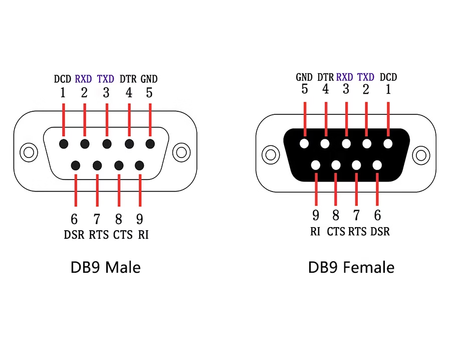
Most embedded links only use three of these nine pins: TX, RX, and ground (2, 3, 5). The rest are hardware flow-control signals, and plenty of modern designs skip them entirely in favor of software handshaking.
DB25 RS-232 Cable Pinout (25-Pin D-Sub)
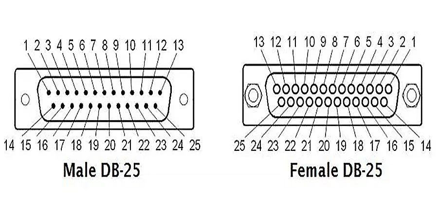
The original RS-232 spec called for a 25-pin connector. You won’t find DB25 on a modern laptop, but it still shows up on an older RS-232 cable or legacy industrial gear. The extra pins were meant to support a second communication channel, though almost no equipment in the real world ever used it. That leaves only a handful of pins that actually matter on a DB25.
| Pin | Signal | Name | Direction |
|---|---|---|---|
| 1 | — | Protective/Shield Ground | — |
| 2 | TXD | Transmit Data | OUT |
| 3 | RXD | Receive Data | IN |
| 4 | RTS | Request To Send | OUT |
| 5 | CTS | Clear To Send | IN |
| 6 | DSR | Data Set Ready | IN |
| 7 | SGND | Signal Ground | — |
| 8 | DCD | Data Carrier Detect | IN |
| 20 | DTR | Data Terminal Ready | OUT |
| 22 | RI | Ring Indicator | IN |
Pins 12 through 19, plus 21 and 23 through 25, are secondary or reserved and can usually be left alone. Same rule as DB9: a one-way link only needs TX, RX, and ground.
🔌 Building an embedded application that needs a durable RS-232 connection?
Romtronic handles the whole cable assembly process, from prototyping through full production, to ISO and IATF standards.
📩 Request a quote →
Straight-Through vs. Null-Modem RS-232 Cables
A straight-through RS-232 cable connects matching pins, TX to TX, RX to RX. Use it when you’re linking a DTE (a computer) to a DCE (a modem or peripheral device). That’s the standard case.
However, if you need to connect two DTE devices directly, say two PCs, or two embedded boards that both identify as DTE, a straight cable won’t work. In that case you need a null-modem (crossover) cable, which swaps TX and RX (and often RTS/CTS) so each side can actually hear the other.
For most embedded projects, a straight cable is all you’ll ever need. If you do end up with two DTE devices on your hands, a null-modem adapter or a gender changer fixes the mismatch without re-terminating anything.
RS-232 Cable vs. RS-485: Which One Do You Actually Need?

Both are EIA/TIA serial standards, but they were built for different jobs, and mixing them up is one of the more common wiring mistakes in embedded design.
RS-232 vs. RS-485 at a Glance
| RS-232 | RS-485 | |
|---|---|---|
| Signaling | Single-ended, referenced to ground | Differential, two-wire balanced pair |
| Topology | Point-to-point (one transmitter, one receiver) | Multi-drop bus, up to 32 transceivers |
| Max distance | ~15 m (50 ft) reference figure, set by a 2,500 pF cable capacitance limit rather than a fixed length | ~1,200 m (4,000 ft) |
| Max data rate | 20 Kbps per the TIA-232-F spec (short, low-capacitance cable can go higher) | Up to ~10 Mbps, depending on distance |
| Duplex | Full-duplex, separate TX/RX | Half-duplex (2-wire) or full-duplex (4-wire) |
| Noise immunity | Lower, sensitive to ground-potential differences | Higher, differential signaling rejects common-mode noise |
| Typical connector | DB9 / DB25 | Terminal block, DB9, or M12 (no fixed standard) |
How Far Can an RS-232 Cable Really Run?
That “15 m” figure gets repeated everywhere without context, so it’s worth unpacking. Older write-ups treat it as a hard limit, but since the TIA-232-D revision, the actual standard specifies a maximum cable capacitance of 2,500 pF, not a fixed distance. In other words, fifteen meters is simply what that limit works out to on a typical cable at 50 pF/m. Use a lower-capacitance RS-232 cable and you can run measurably farther at the same data rate. Push the baud rate higher, on the other hand, and the usable distance shrinks.
When to Choose RS-232 vs. RS-485
Go with RS-232 if you’re linking two devices over a short run and simplicity matters more than distance or noise immunity: a PC talking to a legacy instrument, a debug console, a point-to-point link inside an enclosure.
By contrast, go with RS-485 if you need to network several devices on one bus, run cable a long way, or work in an electrically noisy environment where RS-232’s single-ended signaling starts to fall apart.
Is RS-232 Obsolete in 2026?
Not for embedded and industrial work. USB and Ethernet took over the consumer side years ago, but RS-232 sticks around wherever equipment stays in service for 10 to 20 years or longer. For a new design that needs multi-device networking or longer cable runs, RS-485 (or a USB/Ethernet bridge) is usually the better call. But for a simple point-to-point link into existing hardware, an RS-232 cable is still the path of least resistance. And if you’re bridging RS-232 gear to a modern USB-C host, see our USB-C to RS-232 (DB9) adapter guide.
EMI and Shielding: Keeping an RS-232 Cable Clean
RS-232’s single-ended, ground-referenced signaling is what makes it vulnerable to electrical noise in the first place. Motors, VFD drives, and switching power supplies sitting nearby can all degrade or corrupt the signal. As a result, how the RS-232 cable itself is built determines whether that noise ever reaches your data lines.
Twisted Conductors
Twisting the TX/RX pairs cancels out most externally induced noise before it hits the receiver. In addition, low-capacitance insulation helps keep signal edges clean over longer runs.
Shielding Types
A well-built RS-232 cable usually combines two types of shielding around the conductor bundle. Foil shielding, for instance, wraps the cable with full coverage and blocks high-frequency noise well, but it’s fragile on its own and tears easily with flexing. Braided copper shielding, on the other hand, handles lower-frequency interference and holds up mechanically, though it typically doesn’t reach 100% coverage. Combine the two, in a foil-braid construction, and you get near-complete EMI immunity plus the durability to survive real-world handling. That combination is standard on industrial-grade RS-232 cable.
Connector-Level Shielding
None of that matters if the termination is weak. Metal connector shells or backshells carry the shield continuously from the cable jacket to the mating port. So if you terminate a foil-braid cable into a plastic, unshielded connector, you lose most of the protection right at the interface. Instead, look for 360° shielded terminations and metal EMI/RFI hoods on your DB9 or DB25 connectors.
Proper Grounding
Shielding only works with a proper low-impedance ground path. Ground the shield at one end only, since grounding at both ends can create loops that introduce noise instead of removing it. For more on shield types and grounding strategy across different cable families, see our cable shielding guide.
📌 Running RS-232 near motors, VFDs, or other high-EMI equipment?
Romtronic builds foil-braid shielded RS-232 assemblies with metal-shell connectors for noisy industrial environments.
👉 Discuss your shielding requirements →
RS-232 Cable Quick Reference Table
| Connector | Pin Count | Key Signals | Typical Use |
|---|---|---|---|
| DB9 (DE-9) | 9 | TX, RX, GND, RTS, CTS | Modern serial ports (PCs, controllers) |
| DB25 | 25 | TX, RX, GND, DTR, DCD, RTS, CTS, RI | Legacy RS-232C equipment |
DB9 is smaller and dominates new equipment, while DB25 was the original RS-232C connector and still turns up on older industrial gear. Some RS-232 cable assemblies pair a DB25 on one end with a DB9 on the other; in that case, only the matching signals get wired and everything else stays unused.
🔌 Ready to order a custom RS-232 cable assembly?
Browse our DB9, DB25, and hybrid RS-232-to-USB/TTL configurations, or request a quote with your specific pinout.
👉 View our Custom RS232 Cables →
FAQ
A: No. Microcontrollers run 0–5V TTL logic, while RS-232 swings to roughly ±12V in practice. Because of that, you need a level shifter, like a MAX232, in between.
A: Only when both ends are DTE, like two PCs connected directly. If one end is a DCE (a modem or serial device), a straight-through cable is what you want.
A: No. For a basic one-way link, TX, RX, and ground get the job done. Leave RTS/CTS disconnected if you’re not using hardware flow control.
A: RS-232 for a simple point-to-point link under roughly 15 meters. RS-485 if you’re networking multiple devices, running longer cable, or working in a high-EMI industrial setting.
A: Yes, especially in electrically noisy environments. A foil-braid shielded cable with metal-shell connectors and single-point grounding is the standard way to keep EMI/RFI from corrupting the signal. Unshielded cable is fine only in low-noise settings.
A: Not for embedded and industrial applications. It’s disappeared from most consumer gear, but it’s still the default interface on a large installed base of PLCs, lab instruments, and legacy machine controllers.
References
- Telecommunications Industry Association, TIA-232-F, Interface Between Data Terminal Equipment and Data Circuit-Terminating Equipment Employing Serial Binary Data Interchange (formerly EIA RS-232), 1997. Governs signal levels, the capacitance-based length limit, and DB25 pin assignments. View the standard listing · Background overview
- Texas Instruments, Interface Circuits for TIA/EIA-232-F application report (SLLA037). Driver/receiver electrical specs and the capacitance-based length limit. Read the full application report
- Analog Devices, Fundamentals of RS-232 Serial Communications. Background on the shift from a fixed cable-length spec to the 2,500 pF capacitance limit. Read the article
- Telecommunications Industry Association, TIA-485-A (formerly EIA RS-485). Differential signaling, multi-drop bus, and distance/data-rate specs referenced in the comparison table above. View the standard listing · Background overview
.avif)
Sam Wu is the Marketing Manager at Romtronic, holding a degree in Mechatronics. With 12 years of experience in sales within the electronic wiring harness industry, he manages marketing efforts across Europe. An expert in cable assembly, wiring harnesses, and advanced connectivity solutions, Sam simplifies complex technologies, offering clear, actionable advice to help you confidently navigate your electrical projects.