USB and TTL serial signals are not electrically or logically compatible. The two cannot be connected directly. If you want to communicate with a computer from a TTL-level device, such as a microcontroller, sensor, or embedded module, use a USB-to-TTL adapter.
This article explains the operating principle, required tools, proper wiring methods, software configuration, and reliable troubleshooting steps.
What Is USB to TTL?
“USB-to-TTL” adapters (also known as “USB-UART” bridges) are USB-to-UART “bridge” devices that convert the digital signal format of USB data from a PC to TTL-level (serial) format, which embedded devices can understand.
Common bridge chipsets include:
- CH340 – widely used and cost-effective
- CP2102 – stable and well supported
- FT232 – industrial-grade reliability
- PL2303 – older chipset, driver support may vary by OS version
Why USB Cannot Connect to TTL Directly
USB and TTL differ at both the protocol and electrical levels:
| USB | TTL (UART) |
|---|---|
| Differential signaling (D+ / D−) | Single-ended TX / RX |
| Complex USB protocol | Simple asynchronous serial |
| Requires USB controller | Direct MCU GPIO |
| Fixed USB rules | Flexible baud rates |
A USB-to-TTL adapter handles protocol conversion, logic-level translation, and communication with the operating system via drivers.
Required Tools
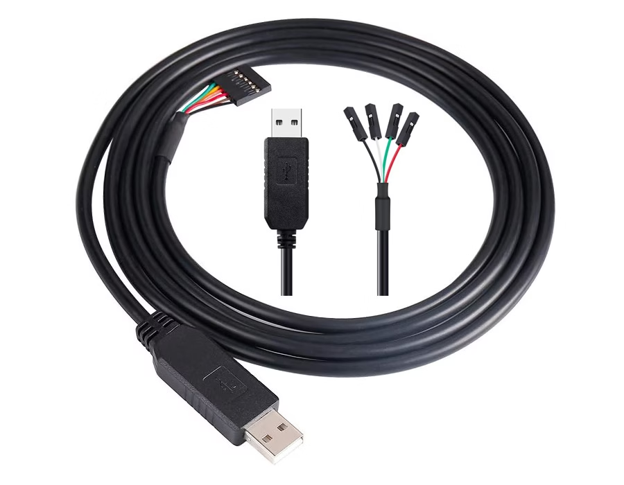
- USB-to-TTL adapter (CH340 / CP2102 / FT232)
- USB cable
- Jumper (Dupont) wires
- Target device (MCU, module, or sensor)
- Serial terminal software
- Windows: PuTTY, SSCOM
- macOS / Linux: screen, minicom
USB to TTL Pin Definition
| Adapter Pin | Device Pin | Description |
|---|---|---|
| GND | GND | Common ground (mandatory) |
| TXD | RXD | Adapter transmits → device receives |
| RXD | TXD | Device transmits → adapter receives |
| VCC (optional) | VCC | Power output (3.3V or 5V only if needed) |
Critical rule:
TX must connect to RX, RX must connect to TX
Never connect TX to TX or RX to RX.
Step-by-Step: How to Connect USB to TTL
Step 1: Install Drivers & Identify the COM Port
- Plug the USB-to-TTL adapter into your computer
- Install drivers if required (most modern OS install automatically)
- Verify the port:
- Windows: Device Manager → Ports (COM & LPT)
- macOS / Linux:
/dev/tty.*or/dev/ttyUSB*
Step 2: Set the Correct Voltage Level (3.3V or 5V)
Most adapters support 3.3V or 5V, selected via a jumper or switch.
- 5V devices: Arduino Uno, Mega
- 3.3V devices: ESP8266, ESP32, STM32, Raspberry Pi
⚠️ Never apply 5V to a 3.3V-only device, as this can permanently damage GPIO pins.
Step 3: Wire the Hardware (Crossover Method)
- GND → GND (connect first)
- TX (adapter) → RX (device)
- RX (adapter) → TX (device)
- VCC (optional)
- Connect only if the adapter is intended to power the device
- Voltage must match exactly
⚠️ Many USB-to-TTL adapters cannot supply sufficient current for Wi-Fi or RF modules (e.g., ESP8266 or ESP32).
For high-current devices, use an external power supply and share the ground.
Step 4: Configure Serial Software
- Open a serial terminal program
- Select the correct COM port
- Set communication parameters:
- Baud rate: must match the device firmware
(for example, 9600, 115200, or device-specific values) - Data bits: 8
- Parity: None
- Stop bits: 1
- Baud rate: must match the device firmware
If the wiring and settings are correct, device output or responses should appear immediately.
Simple TX/RX Loopback Test
If communication does not work, test the adapter itself:
- Disconnect the adapter from the target device
- Short TX and RX together on the adapter
- Open a serial terminal and type characters
Expected result:
The typed characters echo back on the screen, confirming that the adapter, driver, and COM port are functioning correctly.
Common Problems & Solutions
No data output
- TX/RX not crossed
- Wrong COM port
- Baud rate mismatch
Garbled characters
- Incorrect baud rate
- MCU clock configuration mismatch
Adapter not recognised
- Driver missing or incompatible
- Try another USB port (USB 2.0 is often more stable)
Overheating or device damage
- Voltage mismatch
- Incorrect VCC connection
Typical Applications
USB-to-TTL connections are commonly used for:
- Microcontroller programming and firmware flashing
- Serial debugging and log output
- Bootloader access
- Sensor, GPS, and communication module testing
- Embedded system development and manufacturing tests
Conclusion
- USB and TTL are fundamentally different interfaces
- A USB-to-TTL adapter is required as a bridge
- TX/RX crossover and common ground are mandatory
- Voltage level and current capability must be verified
- Loopback testing saves significant debugging time
When wired and configured correctly, USB-to-TTL provides a simple, stable, and reliable communication method for embedded systems.
Related Reading: What is a USB to TTL Serial Cable?
.avif)
Sam Wu is the Marketing Manager at Romtronic, holding a degree in Mechatronics. With 12 years of experience in sales within the electronic wiring harness industry, he manages marketing efforts across Europe. An expert in cable assembly, wiring harnesses, and advanced connectivity solutions, Sam simplifies complex technologies, offering clear, actionable advice to help you confidently navigate your electrical projects.