The majority of today’s electrical systems no longer operate at a single voltage level. Many current products include systems such as EV platforms, UAV systems, Industrial robotics, and medical equipment that operate across multiple voltages and electrical domains (e.g., 5V logic, 12V control circuits, 24V actuators, and sometimes even higher voltages).
Many manufacturers are installing these circuits into a single harness to simplify system integration. This method reduces installation complexity and improves packaging efficiency, but it also introduces additional challenges.
In addition to creating more effective installations, poorly designed multi-voltage harnesses provide pathways for electromechanical interference (EMI), overheating, insulation abuse, and even voltage leakage, resulting in damaged electronics. To create a reliable account, it is essential to plan effectively through electrical, thermal, and mechanical means.
Below are key engineering principles that help ensure multi-voltage harnesses perform reliably over the long term.
What Is a Multi-Voltage Wire Harness?
A wire harness that supports multiple voltages is an electrical assembly that carries different circuits at different voltages within a single package.
A typical system may include:
| Voltage Level | Common Applications |
|---|---|
| 3.3V / 5V | Sensors, microcontrollers, data lines |
| 12V | Control electronics |
| 24V / 48V | Motors, actuators, industrial equipment |
| 110–240V | Main power input |
Having multiple voltage circuits combined into a single harness reduces wiring complexity compared to installing each circuit separately, makes installation easier, and keeps the associated equipment layout organised. However, combining multiple voltage domains into one wire harness requires careful consideration during the design phase to ensure electrical isolation and signal integrity.
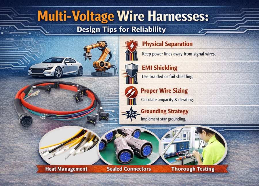
1. Prioritise Physical Separation
The basic principle behind creating reliable equipment is to keep incompatible circuits separate.
Power lines carrying large currents generate strong electromagnetic fields that can adversely affect nearby signal wires. When these circuits run too close together, crosstalk, noise, and other performance issues can arise in the system.
There are several proven methods for minimising this risk:
Zonal routing
High-voltage and/or high-current wires should be routed away from low-voltage signal wires within a harness bundle to the extent feasible. If this cannot be accomplished, create smaller sub-bundles, housed together in the same outer sleeve, to isolate different circuit types.
The 90-degree rule
When power cables and signal wires must cross, they should do so at a 90-degree angle to minimise electromagnetic coupling. Minimise the number of long parallel runs where practicable.
Connector keying
Different connector families or mechanical keying features allow technicians to distinguish between high-voltage power connections and low-voltage signal connections, preventing accidental installation of the wrong type.
2. Manage EMI Through Shielding and Cable Design
In systems with multiple voltages, electromagnetic interference poses challenges for achieving reliable operation.
High-power switching circuits, such as PWM motor drivers, will generate high levels of electrical noise.
To reduce interference, engineers often apply several proven techniques:
Twisted pairs for signal circuits
Twisted pairs are used in many differential communication protocols, including CAN bus, RS-485, and Ethernet. The twisting of the conductors helps ensure that external noise affects both wires equally, allowing the receiver to reject it.
Shielded cables
Braided or foil shielded cables can be used to protect the signalling lines from electrical interference from adjacent power conductors.
Proper shield termination
In many applications, shielded cables are grounded at a single point to avoid ground loops. When using foil-shielded cable, a drain wire provides a low-resistance path to ground for noise picked up by the shield.
These measures help maintain signal stability in electrically noisy environments.
3. Consider Thermal Management and Wire Sizing
Heat is one of the most common causes of long-term harness failure.
The combination of many electrical conductors can trap the heat generated as current flows through them. This buildup of heat increases resistance in the wires, resulting in even more heat.
The power loss equation describes the relationship between current and heat generation:
P = I²R
Because of this relationship, it is essential to consider more than just voltage when calculating wire size. Engineers must also consider these factors:
- Current load requirements
- Bundle density
- Ambient temperature
- Cable length and voltage drop
Each individual wire in a densely packed harness will have its current-carrying capacity (ampacity) reduced by derating factors.
In addition, the choice of quality materials (such as cross-linked polyethylene (XLPE), TXL, or PTFE) for insulating wires will help improve both temperature resistance and long-term durability.
4. Plan Grounding and Voltage Drop Carefully
The importance of a robust grounding architecture increases when multiple electrical voltage types operate together in a single wire harness.
An example of poor grounding is when two or more voltages are referenced to each other, and the reference voltage (ground) is unstable (ground bounce), which can cause problems with sensitive electronics.
Many systems use a star grounding topology, where multiple circuits connect to a common low-impedance ground point. This approach helps prevent unwanted interactions between high-current power circuits and low-voltage signal systems.
Another factor to consider when evaluating ground topologies is voltage drop, especially for longer cable runs. In many industrial designs, electrical engineers generally try to keep their voltage drop to no more than about 3% to ensure proper and stable operation of the system.
Even small voltage losses on low-voltage signal lines can lead to inaccurate sensor readings or unpredictable behaviour.
5. Ensure Mechanical Protection and Strain Relief
The electrical design alone is not sufficient; mechanical reliability is equally important to the harness’s longevity.
The most common failure mechanisms of a harness are related to the termination points rather than the wires themselves. In many cases, terminations include crimp connections and connector interface connections.
To improve durability:
Provide strain relief
Connectors should be designed with proper strain relief features and service loops so that tension does not pull directly on the terminal.
Secure the harness properly.
Clamps and mounting points should support the harness along its routing path, with a spacing of generally 6-12 inches, depending on the application.
Protect against abrasion
Using corrugated tubing, braided sleeving, or protective loom will help to protect the wires from vibration and abrasion.
Use appropriate connectors
In aggressive environments, connectors rated for IP67 or IP6K9K may be required to protect against dust, moisture, and high-pressure cleaning.
In electric vehicles and high-voltage situations, protective orange sleeving is frequently used to visually identify high-voltage circuits and provide safe working conditions during maintenance.
Final Thoughts: Designing for the “Worst Day”
Reliable multi-voltage wire harness design is not just about making a system work on the test bench. The real goal is ensuring the harness continues to function after thousands of hours of vibration, temperature cycling, and electrical stress.
To create a stable, reliable harness that provides optimal functionality throughout the equipment’s life cycle, physical separation, proper shielding methods, thermal derating, and adequate mechanical protection must all be considered in the design.
A well-designed harness becomes a “set-and-forget” component—quietly supporting the system in the background without becoming a maintenance risk.
.avif)
Sam Wu is the Marketing Manager at Romtronic, holding a degree in Mechatronics. With 12 years of experience in sales within the electronic wiring harness industry, he manages marketing efforts across Europe. An expert in cable assembly, wiring harnesses, and advanced connectivity solutions, Sam simplifies complex technologies, offering clear, actionable advice to help you confidently navigate your electrical projects.

