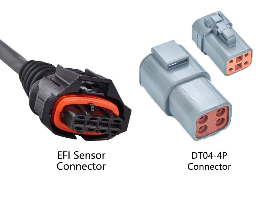
While microchips and PCBs can run reliably for decades, electrical connectors are constantly exposed to physical handling, vibration, and harsh environments. This makes them the most common single point of failure in any electronic system.

Connector failures do not happen at random. They follow predictable patterns caused by mechanical wear, environmental exposure, or improper installation. Understanding these core failure modes is the first step toward building more reliable, long-lasting cable assemblies.
1. Intermittent Connections and Mechanical Wear
This is the familiar “it works if I move the cable” failure.
Why it happens
Repeated mating cycles, vibration, and thermal expansion gradually reduce contact force between mating surfaces. Micro-movement between contacts—known as fretting—wears plating and increases contact resistance.
Typical symptoms
- Intermittent signal loss
- Unstable voltage levels
- Increased electrical noise
How to prevent it
- Review connector mating-cycle ratings during selection
- Use hard gold plating for low-level or signal contacts
- Specify connectors with locking or latching features in vibration-prone applications
In many applications, these issues are addressed at the cable assembly level, where termination quality and strain control are critical.
2. Corrosion and Oxidation
Corrosion creates an insulating oxide layer on contact surfaces, increasing resistance and often leading to localized heating.
Why it happens
- Exposure to moisture or humidity
- Dust, chemical vapors, or contaminants
- Oils and salts transferred from bare-hand handling
Typical symptoms
- Gradual signal degradation
- Unexpected heating at the contact interface
- Eventual loss of continuity
How to prevent it
- Use gold-plated contacts for low-voltage signals
- Match the connector sealing to the environment using appropriate IP ratings.
- Seal backshells with environmental boots or adhesive heat-shrink tubing
Ecological protection is critical in complex wiring systems used in industrial and embedded equipment.
3. Physical Damage and Pin Misalignment
Mechanical damage most often occurs during installation, maintenance, or blind mating.
Why it happens
- Forcing connectors at incorrect angles
- Lack of keying or polarization
- Cable loads pulling directly on terminals
Typical symptoms
- Bent or recessed pins
- Connectors that no longer mate smoothly
- Immediate failure after servicing
How to prevent it
- Use keyed or polarised connector housings
- Select scoop-proof designs where alignment is difficult
- Provide proper strain relief so cable forces are not transferred to contacts
Connector overmolding is a standard solution to reduce both pin damage and long-term mechanical fatigue.
4. Electrical Overload and Overheating
When a connector carries more current than it is designed for, heat builds rapidly. As temperature rises, contact resistance increases, generating even more heat—a feedback loop known as thermal runaway.
Why it happens
- Undersized connectors
- Loose or poorly terminated contacts
- Using signal-grade connectors for power delivery
Typical symptoms
- Discolored or deformed housings
- Burning odor
- Sudden open circuits
How to prevent it
- De-rate the connector current by 20–30% from the datasheet maximum
- Ensure terminations are consistent and mechanically secure
- Validate designs under full load during prototyping, including thermal checks
Proper termination and process control during manufacturing play a significant role in preventing these failures.
5. Improper Connector Selection
A connector may physically fit an application but still be electrically or mechanically unsuitable.
Why it happens
- Ignoring vibration, temperature range, or mating frequency
- Selecting connectors based on cost alone
- Using general-purpose connectors in demanding environments
Typical symptoms
- Premature wear
- Unstable performance under load
- Unexpected field failures
How to prevent it
- Define electrical, mechanical, and environmental requirements early
- Select connectors with adequate design margins
- Consider material quality, plating thickness, and housing durability
Early involvement of an experienced cable and harness manufacturer can significantly reduce selection errors.
6. Installation and Termination Errors
Many connector failures originate during assembly rather than in the field.
Why it happens
- Incorrect crimp height or tooling
- Incomplete seating or partial mating
- Rough handling during installation
Typical symptoms
- High contact resistance
- Wire pull-out
- Early failure despite passing initial tests
How to prevent it
- Use calibrated crimp tools matched to the terminal system
- Apply visual inspection and pull-force testing
- Train installers to stop if a connector does not mate smoothly
Controlled production processes are essential for high-reliability cable assemblies.
Why Material Quality Matters
Quality of manufacture plays an integral part in connector reliability. Terminal burrs cause terminal insertion damage; consistent plating thickness provides stable contact resistance; and properly designed contact springs maintain their normal force for an extended period. Poor material consistency can cause connectors to fail well below their rated limits.
Quick Reference: Failure vs. Prevention
| Failure Mode | Common Symptom | Prevention |
|---|---|---|
| Fretting wear | Intermittent signal | Locking connectors, gold plating |
| Oxidation | High resistance | Environmental sealing |
| Bent pins | Mating failure | Keyed or polarized housings |
| Overheating | Melting or odor | Current de-rating |
| Mechanical fatigue | Broken conductors | Proper strain relief |
Conclusion
It is rarely a mystery why a connector has failed; in nearly every case, the failure can be traced to well-defined, predictable stresses on the connector, typically due to mechanical wear, environmental exposure, electrical overloads, or poor installation practices.
Engineers can effectively eliminate most connector-related failures before the product reaches the field by selecting appropriate connectors, designing connectors with realistic engineering tolerances, and controlling assembly quality.
The connection is the basis for good system performance and efficient operation.
Connector Failures FAQ
Answer: Vibration and thermal expansion. These forces cause microscopic rubbing that wears away contact plating, exposing the base metals to oxidation. Use gold plating and locking latches to stop it.
Answer: Thermal runaway. Loose or undersized contacts generate localized heat. As temperatures rise, contact resistance increases, creating a feedback loop that melts the plastic.
Answer: Use keyed, polarized, or scoop-proof connectors. These designs physically force correct alignment before the delicate pins can make contact.
Answer: Bad crimping. Using uncalibrated tools or incorrect crimp heights causes loose connections or severed wire strands. Always use manufacturer-specified tooling for a gas-tight seal.
Answer: No. While gold does not oxidize, thin plating has microscopic pores that allow the underlying base metal to corrode. For wet areas, you must combine gold plating with IP-rated environmental seals.
.avif)
Sam Wu is the Marketing Manager at Romtronic, holding a degree in Mechatronics. With 12 years of experience in sales within the electronic wiring harness industry, he manages marketing efforts across Europe. An expert in cable assembly, wiring harnesses, and advanced connectivity solutions, Sam simplifies complex technologies, offering clear, actionable advice to help you confidently navigate your electrical projects.