In today’s electrical systems across various industries—from industrial robots to aerospace electronics—wiring harnesses serve as the “circulatory system” of machines, defining their functional scope and capabilities. Despite their critical importance, it is estimated that 40% of system failures are attributed to improper wiring harness layout design rather than software issues.
Improper harness layout design can introduce issues such as fatigue, insulation degradation, and electromagnetic interference (EMI) crosstalk into the system. Implementing a reliability-centred harness layout (RCL) will reduce the likelihood of these failure modes and significantly lower the user’s total cost of ownership (TCO).
1. Strategic Routing: Mitigating Mechanical & Thermal Stress
Mechanical fatigue is the primary failure mode in industrial wiring. To ensure long-term durability, wiring routes with lower stress should be prioritised over the shortest paths.
- Vibration Isolation: In high-vibration areas, specialised clamps with rubber bushings should be used to isolate the wiring harness from chassis vibrations. This is particularly critical for medical device wiring harnesses, where signal accuracy is paramount.
- Thermal Offset: Maintain a safety buffer distance of at least 50 mm (2 inches) from components with temperatures exceeding 85°C. In extremely high-temperature environments, heat-resistant sleeving should be used to prevent “dry rot” of the insulation.
2. Bend Radius Integrity: Implementing IPC-620 Standards
Improper bend management can cause cold working effects in the copper strands, leading to intermittent open circuits and signal degradation.
- Static Layouts: Strictly adhere to the IPC-WHMA-A-620 standard, ensuring a minimum bend radius of 8 to 10 times the outer diameter (OD).
- Dynamic/High-Flex Layouts: For robotic connectors, the bend radius should be increased to 12-15 times the outer diameter (OD). Using specialised robotic wire-harness materials ensures a uniform distribution of torsional stress.
3. Signal Integrity & EMC Architecture
In complex B2B systems, electromagnetic compatibility (EMC) is non-negotiable. Improper layout is the primary cause of data corruption.
- Orthogonal Routing: When power lines and data lines must cross, ensure they intersect at a right angle (90°) to minimise inductive coupling.
- Physical Segregation: Maintain a minimum distance of 100 millimetres between unshielded power cables and sensitive sensor harnesses; this is a standard requirement in automotive wire harness design.
4. Maintenance-Optimised Accessibility (The “Service UX”)
A common pitfall in engineering design is prioritising manufacturing convenience over on-site maintainability.
- The Service Loop Strategy: Leave 3–5 inches (75–125 mm) of slack near connection points. This allows for rewiring without replacing the entire harness.
- Modular Architecture: Using plug-and-swap modules, the integrated wiring harness is divided into separate sections. This approach is particularly effective in industrial wiring harness solutions, as rapid fault isolation can reduce repair time from hours to minutes.
5. Targeted Protection & Permanent Identification
- Zonal Protection: Please use braided polyester sleeves or corrugated conduits specifically for bulkhead penetrations and high-friction areas.
- Identification: Please use UV-resistant laser marking. In oily environments, adhesive tape tends to peel off, making it impossible to identify components during critical maintenance.
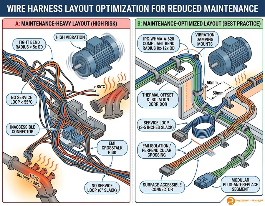
Comparison: Maintenance-Heavy vs Optimised Layouts
| Design Factor | Maintenance-Heavy (High Risk) | Optimized Layout (Best Practice) |
| Bend Radius | < 5x OD (Tight bends) | 8x – 12x OD (IPC-620 Compliant) |
| Routing Path | Shortest path (Crossing heat/vibe) | Stress-free corridors / Rigid frames |
| Connectivity | Buried/Hidden connectors | Surface-accessible / Modular segments |
| EMI Strategy | Bundled Power & Signal | Perpendicular crossing / Segregation |
| Future-Proofing | Exact length (No slack) | Service loops (3-5″ slack) |
Conclusion: Engineering Resilience into every Millimetre
A well-designed harness layout is the key to determining whether your equipment operates efficiently or remains idle. By strictly adhering to bend radius limits, electromagnetic interference (EMI) shielding, and modular maintainability principles, you can ensure maximum uptime as a core element of your product design.
At Romtronic, we incorporate these standards into every custom harness assembly we produce.
Ready to optimise your system’s reliability? Contact Romtronic’s Engineering Team Today
.avif)
Sam Wu is the Marketing Manager at Romtronic, holding a degree in Mechatronics. With 12 years of experience in sales within the electronic wiring harness industry, he manages marketing efforts across Europe. An expert in cable assembly, wiring harnesses, and advanced connectivity solutions, Sam simplifies complex technologies, offering clear, actionable advice to help you confidently navigate your electrical projects.

