


Real-World Defense Against Molten Slag and Arc Noise
A reliable robotic welding wire harness has to survive one of the roughest environments any cable ever faces. A 6-axis welding robot works right inside the splash zone, with molten slag hitting nearby surfaces at roughly 1200°C. The internal wiring sits inches from that heat, soaking up UV radiation and getting hammered by the electromagnetic noise every arc strike throws off. Standard control cable just isn’t built for that.
Here’s what actually happens when it fails: hot spatter burns through basic PVC insulation, and the exposed copper underneath can short out and take an expensive PLC rack down with it. Meanwhile, voltage spikes from the MIG/TIG power unit punch straight through weak shielding and bleed into your CAN bus or industrial Ethernet lines. That’s when you start seeing ghost tracking errors, corrupted data packets, or an emergency stop that fires for no visible reason — and the line goes down.
| Hazard | What It Does to Standard Cable |
|---|---|
| High-amp welding arcs | Continuous high-frequency electrical noise bleed |
| 1200°C molten slag | Jacket meltdown, immediate copper exposure |
| Continuous multi-axis torsion | Shielding fatigue, internal wire snapping |
Romtronic builds a robotic welding wire harness around this exact failure profile — thermal armor, real grounding geometry, and torsion-rated internals — so the cell keeps running instead of drifting or tripping out.
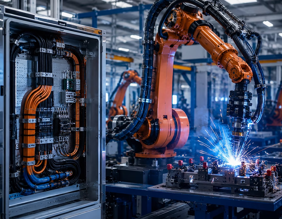
What a Robotic Welding Wire Harness Actually Needs to Survive
We don’t retrofit off-the-shelf cable for weld cells. We build around three specific failure points instead.
1. Slag-Repellent, Cross-Linked Jacketing
Standard jacket material will bake, or straight-up liquefy, a few inches from a continuous arc — that’s not a defect; it’s just what PVC does at those temperatures. So for this application, we turn to fluoropolymers and cross-linked elastomers instead. We cover the reasoning in more depth in our guide on choosing materials for extreme-temperature harnesses, but the short version is this: these chemistries hold their structural strength and dielectric properties under sustained radiant heat, and the surface stays slick enough that molten slag beads off instead of soaking in.
2. Double-Shielded Noise Isolation
Welding arcs are electrically loud, so we don’t rely on a single shield layer. Signal pairs get a 100%-coverage aluminum-mylar foil wrap first, then a tinned-copper braid rated above 95% surface density on top. Two layers, two different noise-rejection mechanisms — foil handles high-frequency bleed, braid handles the rest. That combination keeps positioning and tracking data clean, even a few feet from an active arc.
3. Torsion-Rated, Low-Friction Internals
A 6-axis wrist twists constantly, and that torsion is what actually breaks conductors over time — not one big event, just fatigue building up bend after bend. We build the internal conductors from IEC 60228 Class 6 extra-fine-stranded copper, wrapped in low-friction PTFE separation tape so the bundle can twist and glide instead of binding against itself. It’s the same approach behind our high-flex life cabling for 7-axis collaborative robots, which we’ve validated past 20 million flex cycles.
Welding Cell Harness Configuration Matrix
| Zone | Core Hazard | Engineering Fix |
|---|---|---|
| Weld Torch & Wire Feeder Umbilicals | Flying slag, radiant heat, severe axis-6 wrist twisting | High-flex PUR control lines with heavy-wall, self-extinguishing silicone breakout boots |
| Seam-Tracking Cameras & Vision Links | EMI from arc ignition, metallic dust, UV degradation | Low-capacitance twisted-pair cable under a floating braided shield, overmolded connectors |
| Primary High-Amp Power Trunks | Current surges, internal heat buildup, tight bend radii near the base | Large-gauge conductors in cross-linked, heat-stabilized jacketing |
| Safety Interlocks & Limit Switch I/O | Dragging friction, lubricant exposure, mechanical impact | Locking industrial connectors wrapped in abrasion-resistant Nomex sleeving |
The Two Failures We See Most Often
Slag crust cracking the jacket and back-feeding voltage into the controller. Route standard cable through a weld area, and hot spatter builds up a crust on the jacket over time. Eventually that crust cracks, metallic dust gets into the gap, and you’ve got a short sitting right where it can back-feed a spike into your main controller board. That’s an expensive repair, and it’s avoidable. Flame-retardant fluoropolymer and cross-linked PUR resist slag adhesion, so the jacket doesn’t crack and the insulation holds up at temperatures that would cook a standard cable.
Seam-tracking drift from EMI bleed. Run a vision or laser sensor cable parallel to a heavy welding current line without real isolation, and arc noise will distort the signal. The controller reads that distortion as positional data, the weld head drifts off the seam, and you get parts that fail QC. Loose terminations make this worse — a marginal crimp on a high-current joint acts like a resistor, heats up, and eventually cooks the housing around it. That’s why we weigh ultrasonic welding against mechanical crimping for every high-exposure joint on the arm, rather than defaulting to one method everywhere.
Manufacturing Standards and QC
Every harness goes through the same validation sequence before it ships:
Inbound Component Testing → Real-Time Crimp Monitoring → Three-Stage Quality Testing Gate → Zero-Defect Shipment
| Gate | Test | What It Confirms |
|---|---|---|
| 1 | Post-crimp optical inspection | Crimp geometry and contact placement |
| 2 | High-voltage dielectric test | Insulation integrity at rated voltage |
| 3 | Mechanical pull & continuity test | Termination strength and circuit continuity |
Terminal crimps, grounding joints, and wire dressing follow workmanship criteria under IPC/WHMA-A-620. (Confirm internally which Class — 1, 2, or 3 — your QC team certifies these builds to, so the published claim matches your documented process.) Our lines also run High-Mix, Low-Volume (HMLV) production, verified independently through our own in-house testing lab, so a specialized, low-volume welding-cell configuration doesn’t get stuck behind a standard minimum order quantity. For broader context on where this kind of demand is headed, trade coverage has tracked growing demand for high-flex, purpose-built interconnects as automated welding and robotics platforms scale up.
FAQ
A: Our weld-cell harnesses are built to survive continuous exposure near 1200°C molten spatter zones, using cross-linked and fluoropolymer jacketing rather than standard PVC.
A: A double-shield design: 100%-coverage aluminum-mylar foil under a tinned-copper braid rated above 95% surface density, which handles both high-frequency and broadband EMI.
A: IEC 60228 Class 6 extra-fine-stranded copper, wrapped in low-friction PTFE tape so the bundle twists instead of binding and fatiguing.
A: Workmanship criteria aligned with IPC/WHMA-A-620, verified through a three-stage gate: post-crimp optical inspection, high-voltage dielectric testing, and mechanical pull/continuity testing.
A: Yes — our lines are set up for High-Mix, Low-Volume production, so a one-off or niche configuration isn’t held to a standard minimum order quantity.
Talk to Our Wiring Engineers
If wiring failures are eating into your welding line’s uptime, or you’re specifying a new cell and want to get it right the first time, send us your files. Upload your 2D wiring layouts, 3D models, or BOM, and we’ll run a full DFM review and send a production quote within 24 hours.
Accepted formats: .jpg, .png, .xlsx, .pdf, .zip — max 10MB. Submissions are covered under our internal NDA policy.