


Solving the Tight Space and Weight Constraints of Anthropomorphic Motion
A reliable humanoid exoskeleton wire harness has to solve one of the hardest packaging problems in robotics. Humanoid robots and wearable medical exoskeletons sit at the outer edge of high-density electronic design. Unlike bulky, stationary industrial machinery, these bio-mimetic systems pack dozens of actuators, high-torque motors, control boards, and feedback sensors into a narrow, human-sized footprint. As a result, engineers must plan every millimeter of routing space inside the carbon-fiber or aluminum limbs from the start, rather than fitting wiring in afterward.
- Multi-Axis Actuator Clusters → High torque, heavy current spikes, rapid heat buildup
- IMUs, Tactile & Vision Sensors → Ultra-high-speed data lanes, extreme EMI susceptibility
- Battery Systems & Power Rails → Strict space demands, severe weight constraints
These systems move dynamically, often mimicking human gaits and delicate hand movements. As a result, the internal harness is subjected to constant physical stress. It must flex and twist through tight joints while maintaining signal integrity. If a wire bundle lacks sufficient structural flexibility, constant friction within a compact actuator joint will quickly fatigue the conductors. That fatigue causes broken strands, micro-shorts, or packet loss — and any of those can make a humanoid lose its balance or trigger an exoskeleton safety lock without warning.
To solve these problems, Romtronic engineers custom, lightweight, ultra-flexible harnesses. Our designs fit strict space constraints while still delivering reliable power and signal throughput.
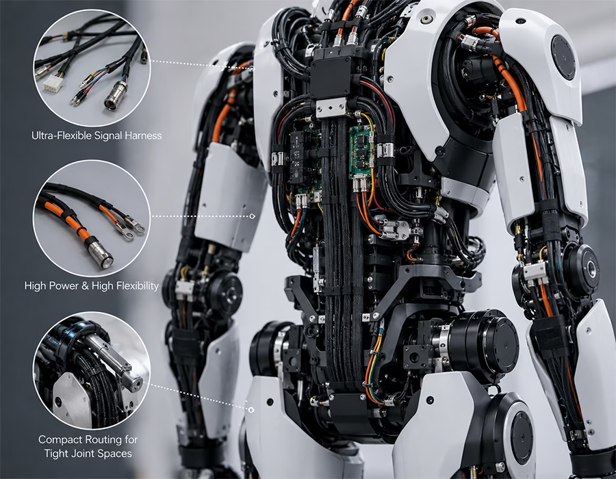
Technical Benchmarks for a Humanoid Exoskeleton Wire Harness
To keep bipedal robots upright and exoskeletons moving naturally with their users, we build every harness assembly around three core specifications.
1. Miniature, High-Flex Wire Alloys
Standard copper wire is too heavy and brittle for a robotic finger actuator or knee joint in continuous motion. So we specify IEC 60228 Class 6 (extra-fine stranded) copper alloys and wrap them in thin-walled fluoropolymer insulation, such as ETFE or FEP. Robotics and drag-chain engineers use this same stranding class for one reason: it distributes bending strain across many fine strands rather than causing work-hardening and cracking, as a solid or coarse-stranded conductor would. The result is a bundle that stays thin and light. It routes easily through confined joint housings without giving up dielectric strength or abrasion resistance.
2. High-Flex Life Cabling for Constant Joint Flexing
Cables that run through multi-axis human joints — such as the shoulder, hip, or ankle — need to withstand millions of bending and twisting cycles without degrading. Our joint harnesses use the same engineering approach as our high-flex life cabling for 7-axis collaborative robots. We’ve validated that design beyond 20 million flex cycles. Applying the same discipline to humanoid and exoskeleton joints gives you long-term continuity. As a result, your cables resist degradation throughout the product’s full service life.
3. High-Density Micro-Interconnects
In humanoid and exoskeleton designs, connector volume is a primary bottleneck. So we specify ultra-compact, high-density micro-pitch connectors with positive active-locking mechanisms. That way, a sudden jolt from walking, jumping, or heavy lifting can’t shake a connector loose mid-stride.
Humanoid Exoskeleton Wire Harness Blueprint
| Zone | Core Hazard | Engineering Fix |
|---|---|---|
| High-Torque Joint Actuators (hip, knee, shoulder) | Heavy instantaneous current spikes, rapid heat buildup, non-stop torsional fatigue | Micro-stranded, large-gauge copper power lines in heat-resistant, low-friction cross-linked jacketing |
| Tactile Hand & Wrist Manipulators | Extremely tight routing paths, hundreds of micro-bends, continuous low-radius flexing | Ultra-fine micro-coaxial or twisted-pair signal lines in thin-wall PTFE wrapping for fluid movement |
| LiDAR, Cameras & Depth Sensor Arrays | High-speed sensor data corruption from nearby motor cables and localized EMI | Low-capacitance twisted-pair cable protected by a 360° floating tinned-copper braided shield |
| Battery Pack & Power Distribution Backbones | Strict payload weight limits, walking-impact vibration, high battery current draws | High-flex silicone power cable with gas-tight crimped lugs and flame-retardant jacketing |
Eliminating Real-World Engineering Glitches in Bio-Mimetic Systems
Preventing Intermittent Joint Drift and Sensor Corruption
Low-voltage signal lines from joint-angle encoders or force sensors often run right alongside high-current motor lines in a narrow limb. Without deliberate isolation, electromagnetic interference is nearly unavoidable in that layout. Left unshielded, high-frequency noise causes packet drops. To the robot controller, a dropped packet can look identical to a tracking error. That false signal can disrupt the entire balance or gait algorithm.
Our design team prevents this with dedicated shielding and grounding configurations. We separate sensitive sensor pairs from power lines using custom spacing protocols and tinned-copper shields. As a result, data lines stay clean enough for steady, real-time control-loop feedback.
Surviving Extremes: Continuous Movement in Harsh Environments
Exoskeletons and search-and-rescue humanoids often operate in punishing conditions: cold at high altitude, direct sunlight, or humid outdoor environments. Standard plastic wire insulation cracks under exactly this kind of temperature swing. That’s why our approach to selecting materials for extreme-temperature harnesses focuses on one thing: keeping flexibility and chemical resistance intact across a wide operating range, not just at room temperature.
Joint connections are especially vulnerable, so the termination method matters just as much as the material choice. During the initial engineering phase, we weigh ultrasonic welding against mechanical crimping for each joint. This way, every build uses the method that yields the lowest-resistance contact for that specific location. Lower resistance, in turn, means less internal heat buildup.
For broader context on why this discipline matters industry-wide, trade coverage of the humanoid robotics sector has increasingly highlighted interconnect and wiring design as one of the harder engineering constraints bipedal platforms face.
Manufacturing Standards & Multi-Stage QC Testing
Every humanoid exoskeleton wire harness we build passes through the same validation sequence before it leaves our facility:
Inbound Component Verification → Real-Time Automated Crimp Monitoring → Three-Stage Quality Testing Gate → Zero-Defect Shipment
| Gate | Test | Purpose |
|---|---|---|
| Gate 1 | Post-crimp optical inspection | Verifies crimp geometry and contact placement |
| Gate 2 | High-voltage dielectric test | Confirms insulation integrity under rated voltage |
| Gate 3 | Mechanical pull & continuity test | Validates termination strength and circuit continuity |
We build every micro-crimp, grounding joint, and shield termination to workmanship criteria aligned with IPC/WHMA-A-620, the industry-consensus standard for cable and wire harness assembly acceptability. (Confirm internally which product Class — 1, 2, or 3 — your QC team certifies these builds to, so the stated class matches your documented process before this goes live.)
Our manufacturing lines are also built for High-Mix, Low-Volume (HMLV) production. That means you can source premium, custom-engineered harnesses for niche, bipedal, or wearable prototype builds. You won’t get forced into restrictive minimum order quantities.
Collaborating with Our Engineering Team
Don’t let wiring issues limit the agility of your humanoid robot or wearable exoskeleton program. Whether you’re re-engineering a complex joint harness or finalizing schematics for a prototype build, our engineering team can help optimize your layout.
Simply upload your 2D wiring layouts, 3D mechanical path models, or Bill of Materials (BOM). Our engineers will then run a full Design for Manufacturability (DFM) review. We’ll return an accurate production quote within 24 hours, with initial engineering feedback within 12 hours.